Update: 10-11-2009 experiment with a end fed wire for 40m (7 MHz).
I had not been active on HF for a while and wanted to make some contacts on the 40 m / 7 MHz band. I don't have room for a half wave 2x 20m dipole so I thought about how mobile antenna's work. These mobile versions are mostly 1/4 wave length ... and vertical.
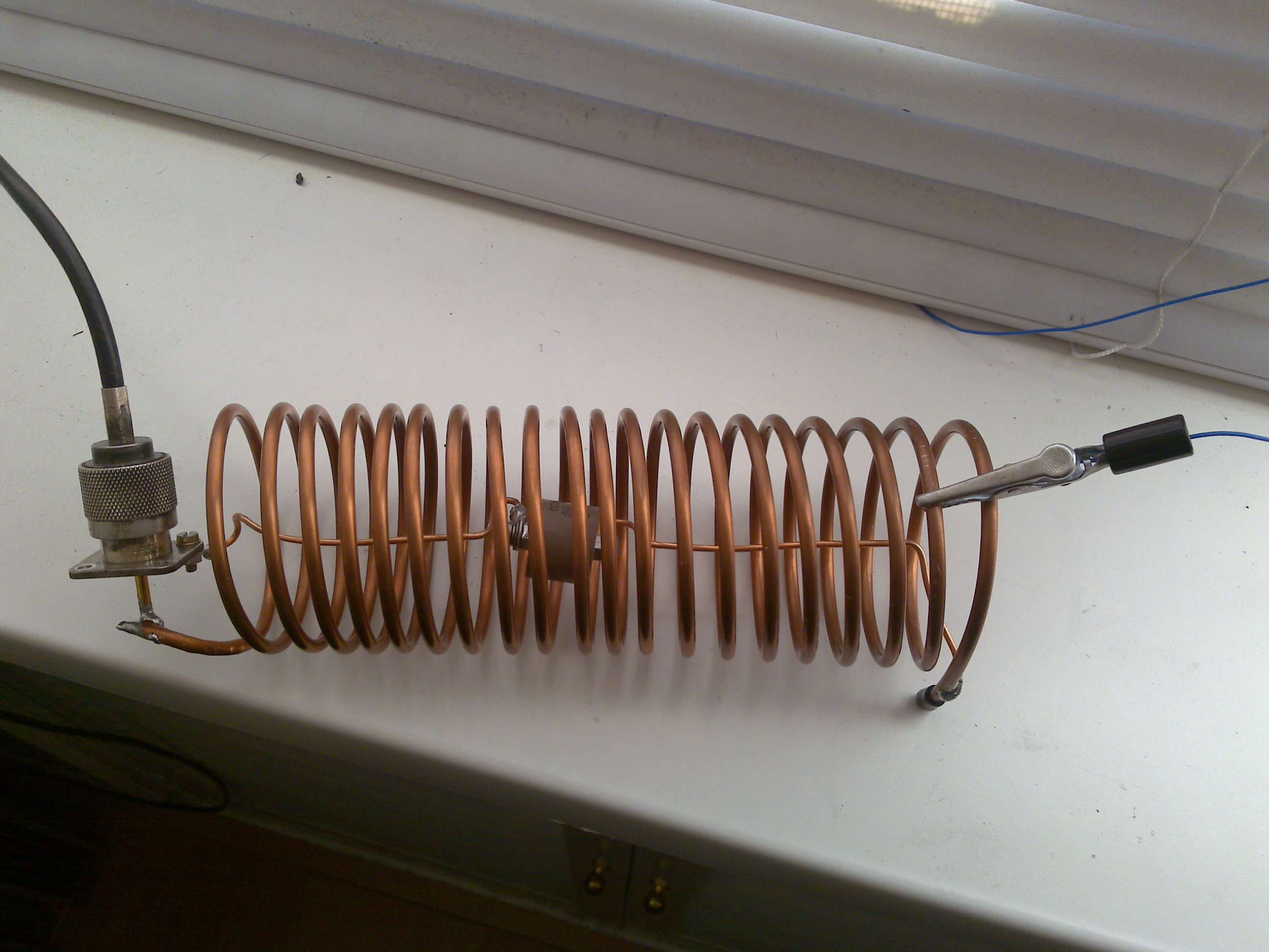
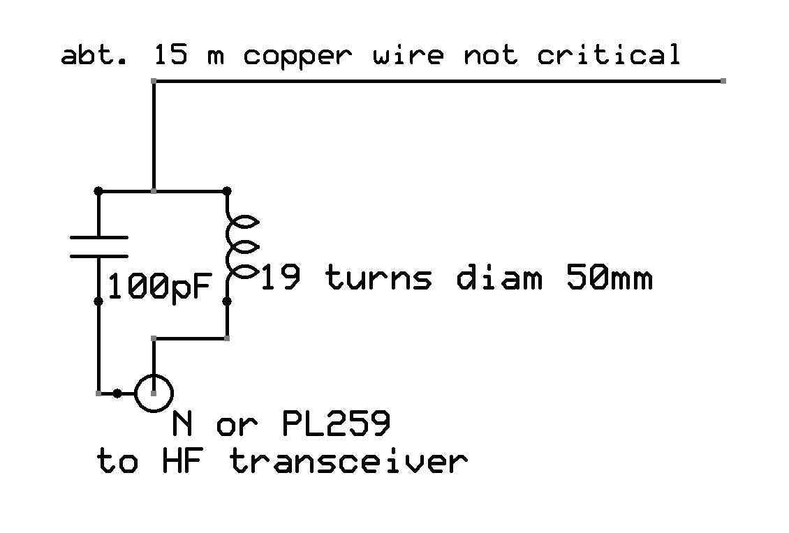
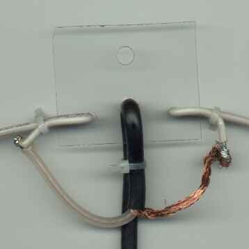
So I made a coil 19 turns of thick copper wire, or in my case a piece of semi-rigid coax with diameter of 50mm. Parallel I put a 100pF high voltage capacitor.
The capacitor was put inside the coil, as is done when using traps for wire antenna's. I put out a lenghth of thin copper wire about 15m long from the shack to the end of the garden.
As you can see on the photo I use a crocodile clamp to be able to attach the wire on different places on the coil. This is usefull to be able to adjust for minimal SWR. In my case the tap was best at 18 turns.
The coil of course has to hang free in the air, but for the photo I put it on the table.
The diagram is as follows and quite easy;
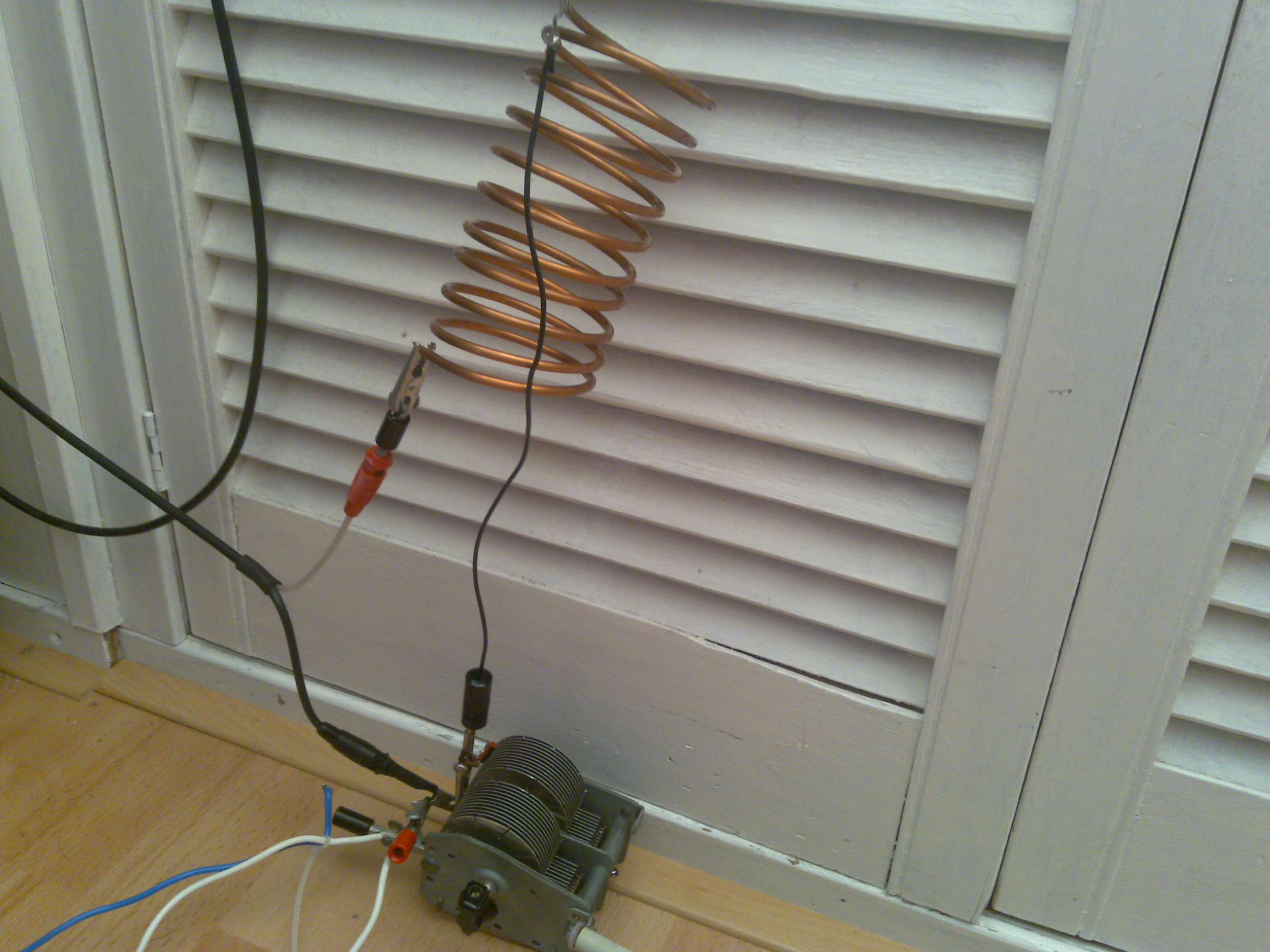
On 16-11-2009 I wanted to try some tests on 3.7 MHz / 80m band. Therefore I used a coil of 10 turns with the same diameter of 50mm.
Instead of a fixed capacitor I used a tunable version and could get a SWR of 1:1 on 80m and also on 10 MHz / 30m band. Al with a single 15m thin copper wire from the shack to the end of the garden.
With some qso's made to OZ, SP, YU and SM all went rather easy with good reports even without conditions. The coil I used for 40m was also used again for qso's and I worked EA8 twice.
The setup of a coil and a capacitor like I used is called "base loading". For better performance you can use a coil half way an vertical antenna or wire, this is "center loaded". For the best result you can put a coil at the end of the wire or in the top of a vertical antenna, which is called "top loading".
The coils are needed to compensate the wire length if it is too short for the band you want to use it on.
The best results are made with half wave sized antenna's ... for 40m you would need about 20m of wire or a 20m long vertical. On 80m this is twice the length.
In my case 15m wire is too short, so I needed an LC combination to match the antenna impedance to my transceivers 50 Ohms. I am planning to rebuild a 27MHz GPA to a HF multiband version. Here I will place a base load LC combination to tune it from 80m to 10m.
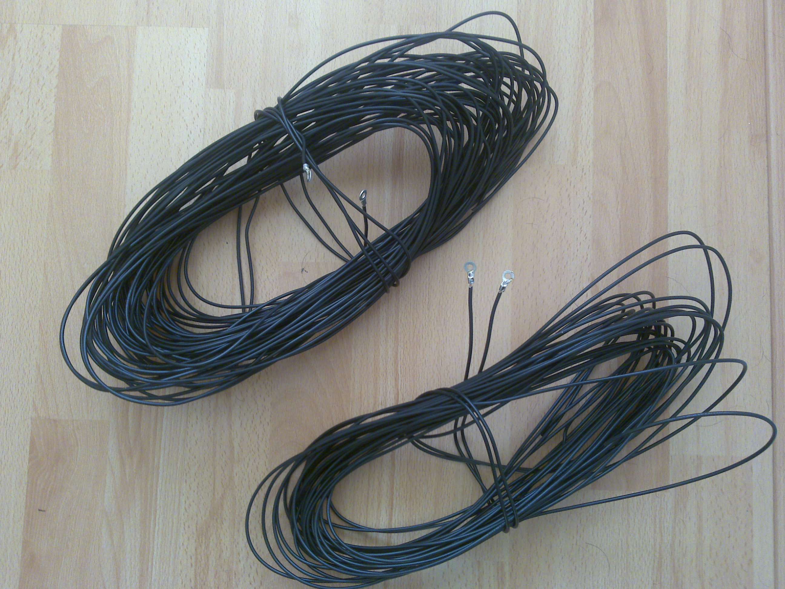
With vertical antenna's you need good grounding. A earth copper pipe into the ground is good for lightning strikes but has not much impact on HF grounding. Therefore I am planning to put 4 radials in the ground. Two times 20m wire and 2x 10m wire.
A photo of the grounding radials made of 1mm2 installation wire which is normally used for 220V systems.
COAX FED DIPOLES:
How to create a simple but effective half wave dipole:
On the bands from 0 - 30 MHz its easy to start with a half wave open dipole. An antenna in resonance can be a whole wave length, half or quarter wave length. There are also other possibilities like 5/8 wave, but are used for vertical antenna�s and mainly for mobile use.
Tip:
if you make a half wave dipole, you normaly spread each side length out horizontaly (180�). If you make an angle upto 90� you create an inverted V. The performance for DX is then better and you also adjust the feedingpoint impedance.
So it�s best to place the dipole where you want it, measure the SWR and then start cutting away small sections at each end to adjust the SWR (standing wave ratio).
SWR is a term used for the adjustment of the coax cable to the dipole. It can be measured with a SWR/Power meter. You measure the reflected power .... you transmit a small amount of power like 10 watts and measure the amount of power which comes back from the dipole to your transceiver. This is actually a loss of power and must be minimised.
The formula .... HALF WAVE.. 150 / F (MHz) = result in meters.
As example a 10 meter dipole is 150 / 28.600 MHz = 5,244 meters.
You then construct two halves of this length (each half is 2,62 meters) to coaxial cable and connect it to your rig. By cutting away small lengths (each side the same ammount) you can adjust the SWR for the best optimisation.
OPEN FEEDER DIPOLES:
If you want to use open feeder wire (impedance 300 or 450 Ohms) you need a antenna tuner to match the feeder to the dipole. An antenna tuner is quite simple to build just by using adjustable capacitors and fixed coils. See the homebrew page via the left kolom for a photo of my antennatuner. Most used are the L and Z-match antenna tuner.
Scematic diagram for an L-match antenna tuner:
Advantage of open a open feeder is that it picks up less noise (QRM) form sparkplugs and computers and its easy to match. The disadvantage is that it radiates more RF power and the change of TVI and interferance on audio and TV equipment is bigger.
More than one dipole direct to your coax:
I use the setup as above for 20/15/10 meters and its works fine. The antenna in resonance will take up all the energy and the other dipoles will not effect its work. You can't put dipoles on one coax for all the HF bands, ... but its also works good for 12/17/30 meter band.
You don't need a 1:1 balun. I use RG58U coax with dipoles for 10/15/20 meters and it works fine.
A balun matches the balanced antenna to the unbalanced coaxial cable and it can lower the noise you might pick up from PC's, traffic etc.
Most people use a balun to minimise the possibility of RF feedback. It can happen that some ammount of power comes back to the transmitter via the outside of the cable. You have a RF problem if you transmit and touch the chassis of your rig ... if you feel a tingle the set is "hot" .. and should be grounded to earth and possibly needs the use of a balun.
A balun can be made by rolling up the coax to abt. 10 windings just below the feeding point at the antenna, or by using a ferrit core and twisting about ten turns of the coax through it.
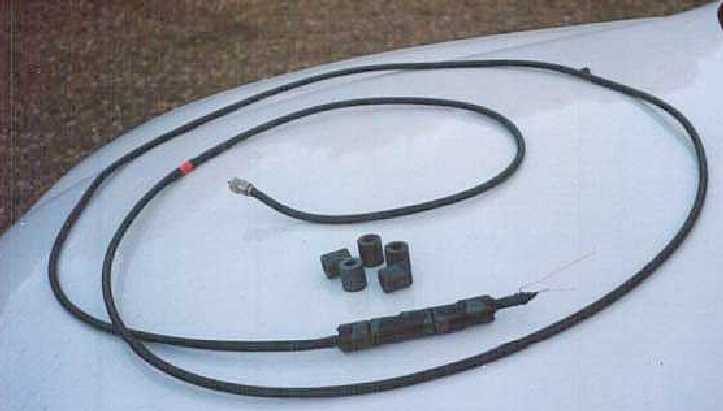
An alternative is putting ferrite beads around the coax cable as shown below:
For more antenna information please check out SM0VPO's website via this link: SM0VPO
A quick holiday construction:
A magnetic loop antenna has good reception quality and picks up less noise compared to a dipole. For transmitting the gain is not verry high and DX is difficult. This antenna is used inside a room when antenna�s can�t be placed on a roof top.
.
Home