50 MHz preamp Gain 26dB with the BFG135
As I had good experience with building preamps for 144 and 430 MHz, I wanted to try a simple design for 50 MHz.
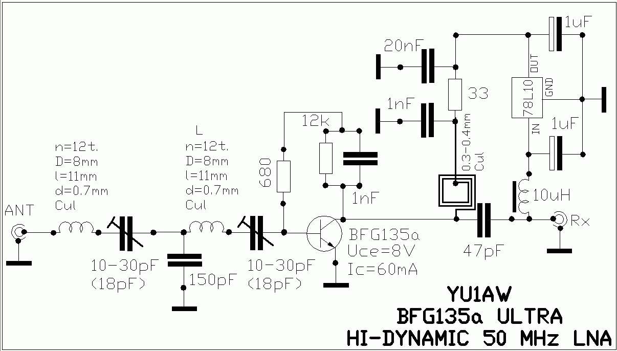
The BFG135a is a cheap transistor and in my view rather strong. It is not easily damaged by static discharge or RF power. The design of YU1AW was slightly changed.
I used a LM317 to control the collector voltage and current instead of a 7810. The collector resistor is fixed 150 Ohms and not 33 Ohms as in the original design.
I used normal 40 pF ceramic trimmers and SMD parts around the BFG connections.
The first result was enough gain but not to be tuned on 50 MHz, coil 2 had to be changed from 12 to 14 turns with diameter 8mm.
After changing the coil the preamp was easily tuned in the 50 MHz band and can also be used for the 70 MHz band as well.
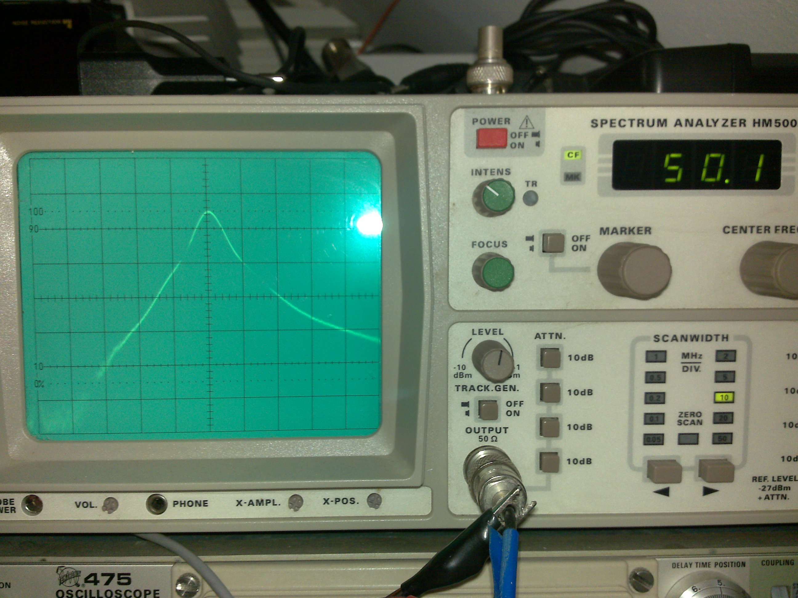
By fiddeling around I noticed that putting a shield in between the coil 1 and 2 at the input side, I could get even better surpression on 144 and 430 MHz. At present I had 55 dB surpression on 144 MHz and 68 dB on 430 MHz. Picture 1 is without the shield and picture 3 with the shield
The gain could be adjusted with the collector voltage. YU1AW gives values of Uce at +8V and Ic at 60mA. I can change this with the 5k potmeter on the LM317


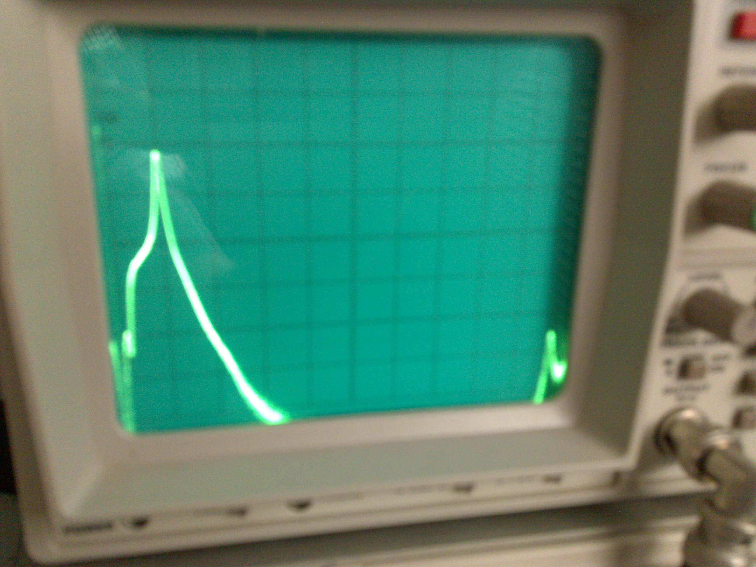
The second peak at the end of the screen is gain at about 500MHz, which is also surpressed when adding the extra shield between the two coils.
With testing on the work bench the gain could be tuned up to more than 26dB. I found that the voltage line was tricky and needed some 1nF, 10nF and 100nF C's to ground and a Fx current coil to stop some parasitic oscillations I noticed when sweeping on the spectrum analyser.
With the lid on the preamp box a little change in gain was noticed but nothing to worry about. My FT100 did not like that much gain and I put in 14dB attenuation to stop teasing its front-end :-)
Below the final version of the YU1AW preamp, not on a fancy printed board, just as the ugly bug method, but it works fine.
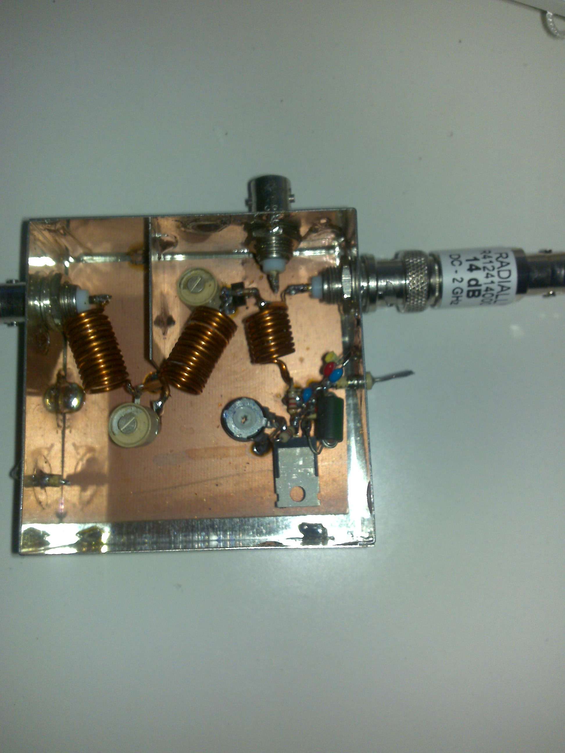
The attenuator at the right side 14dB is only for workbench testing. The BNC connector at the top side is from an old project and has no use.
The Noise Figure NF has still to be measured but it should be around 2dB. You can't get much better with the BFG135, but it is not needed on 50MHz as terestial noise is much more.
NF measurements will probably be made with Peter PA2V.
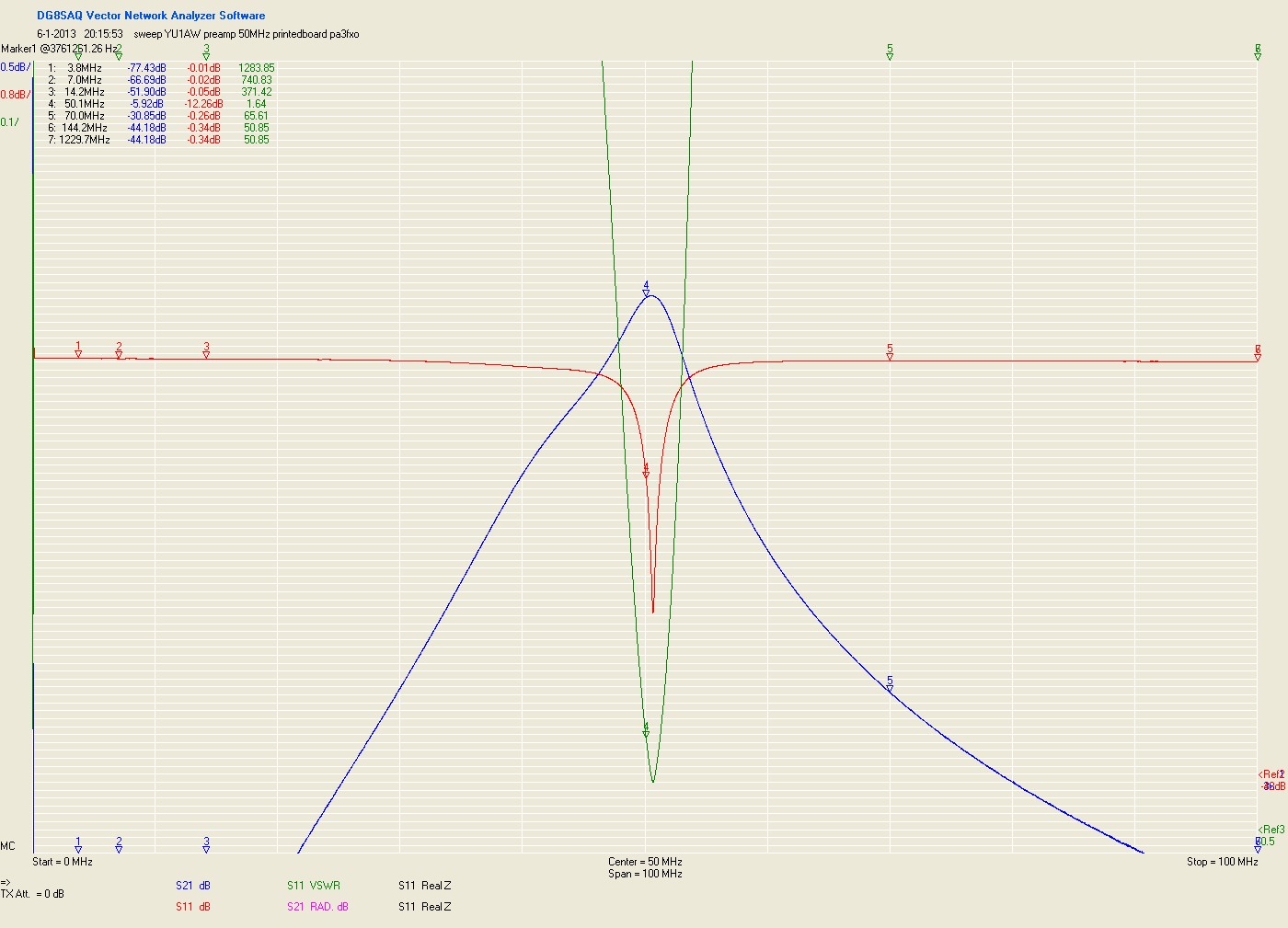
The design of YU1AW with a printed collector coil, which I changed to 8 turns, diameter 7mm and 1mm CuAg (copper wire from an old transformer).
After testing the preamp at PA2V we discovered that it was oscillating and a terrible noise figure was measured. Mmmm .... therefore I orderd a complete preamp set at Colin in England and build this.
The results were fine and I could measure a gain of 25dB and no oscillations. The NF should be around 2dB as PA2V's version.

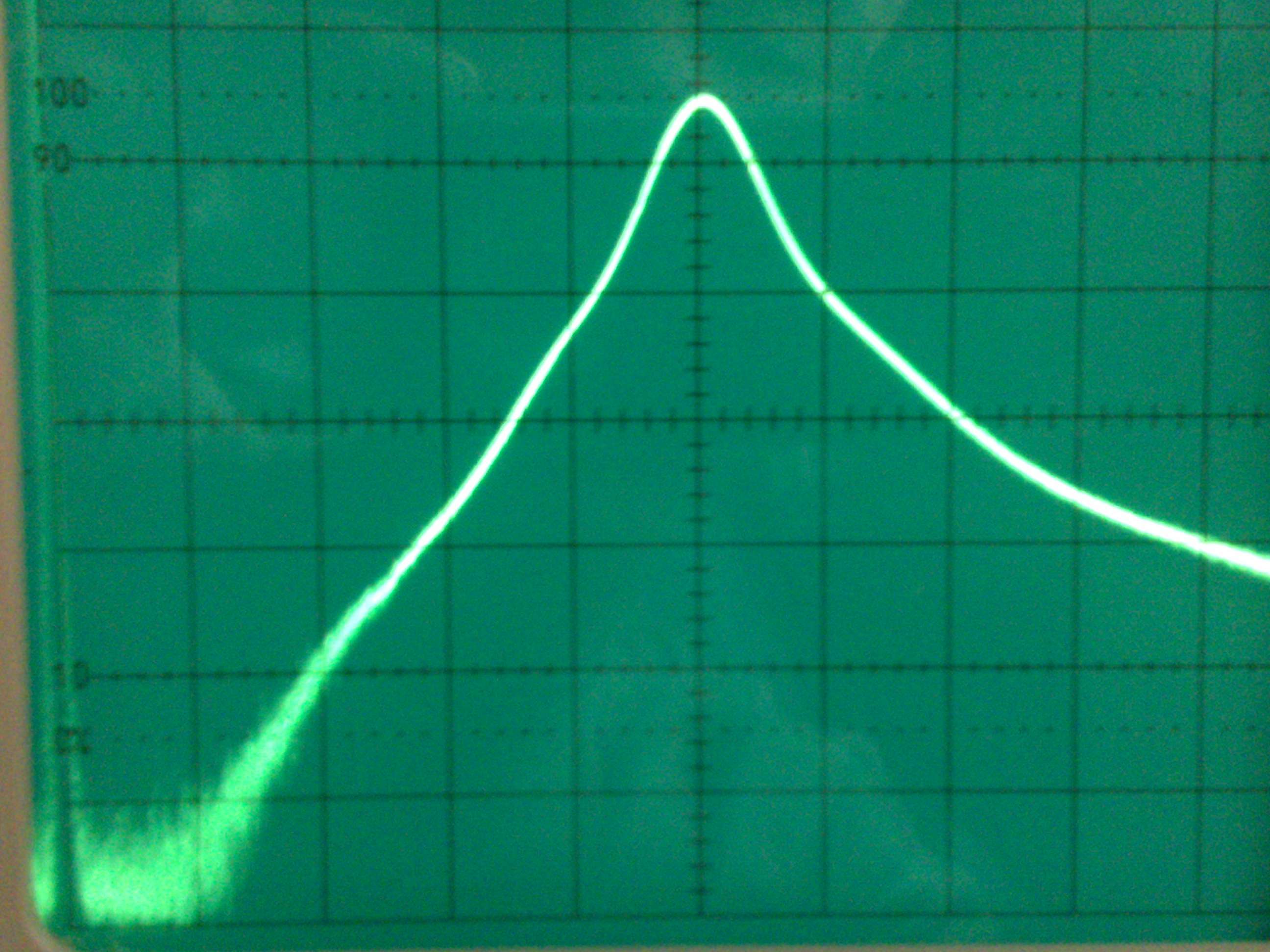
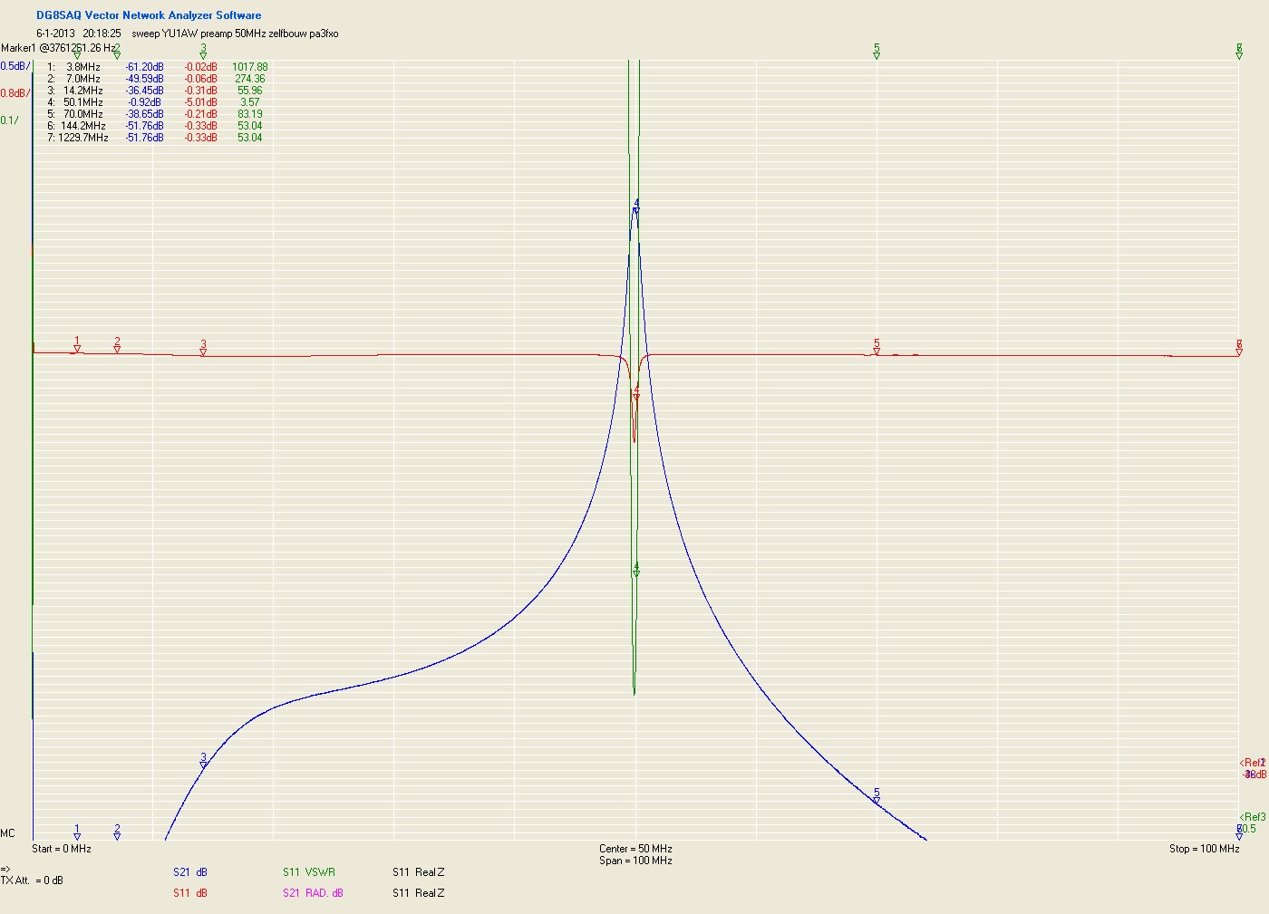
After some tuning both homemade and printed PCB work fine. Here's the sweep with a 30dB attenuator at my homemade VNWA:
20-01-2013 by PA3FXO
Home