4m / 70 MHz transverter home made
As a C-licensed radio amateur I used to be qrv with a temp licence for 50 MHz which had to be submitted by the gouverment of The Netherlands.
There was no commercial equipment for sale and I made a transverter from the UK Six meter group, known as the PW Meon.
This transverter worked fine, but later on I changed over to the design of PA0ZR which was more sensitive and worked better for the RX part.
The output was 7 Watts from a BLW29 and the antenna a home made 3 element Yagi.
As the 4 meter band / 70 MHz was released within some European countrys, it's only a matter of time before The Netherlands will do the same.
I descided to change the old 6m transverter to 4m. This is only 20 MHz difference and it should not be to hard to do.
The RX part needed another cristal for the LO. I needed 42 MHz xtal but in the junk box I found 41.666 MHz + input from my HF set at 28.433 MHz gives 70.2 MHz.
That was easy and only slight adjustment of the trimmers was needed. I did not even bother to change some capacitor values in the filter part.
The TX part was also easily adjusted and with a few mW input I had 5 Watts output on 12V. Turning up the voltage resulted in more than 7 Watts ....talking about QRO :-)
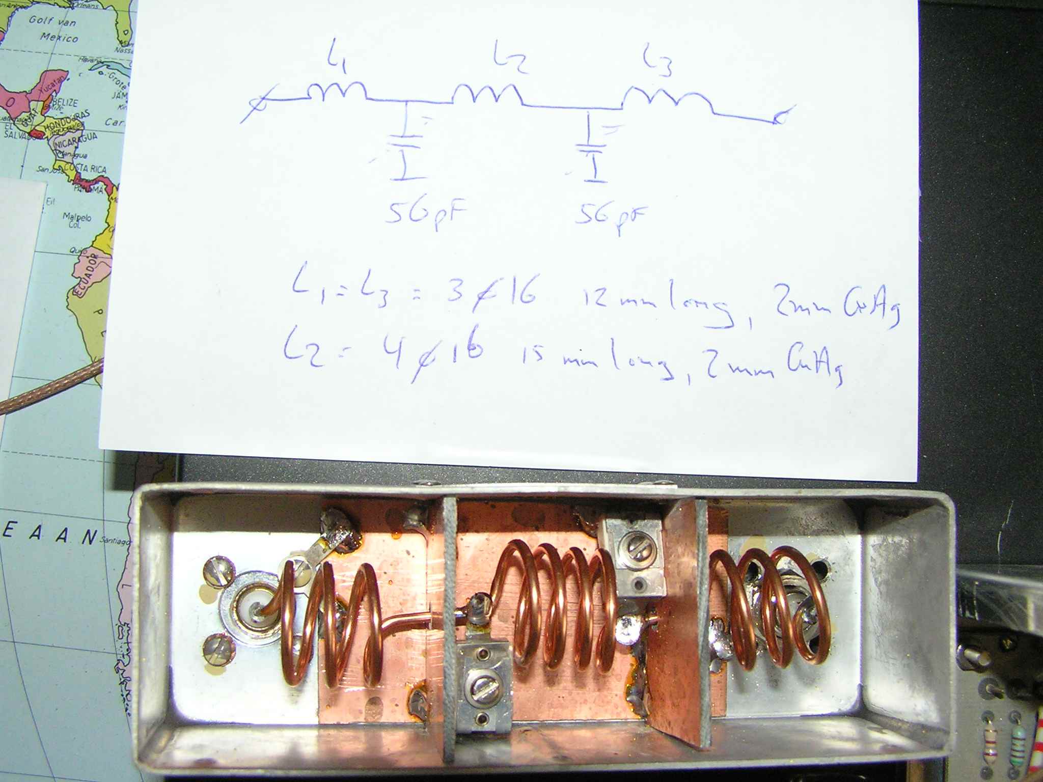
To eliminate some harmonics I build a 70 MHz lowpass filter:


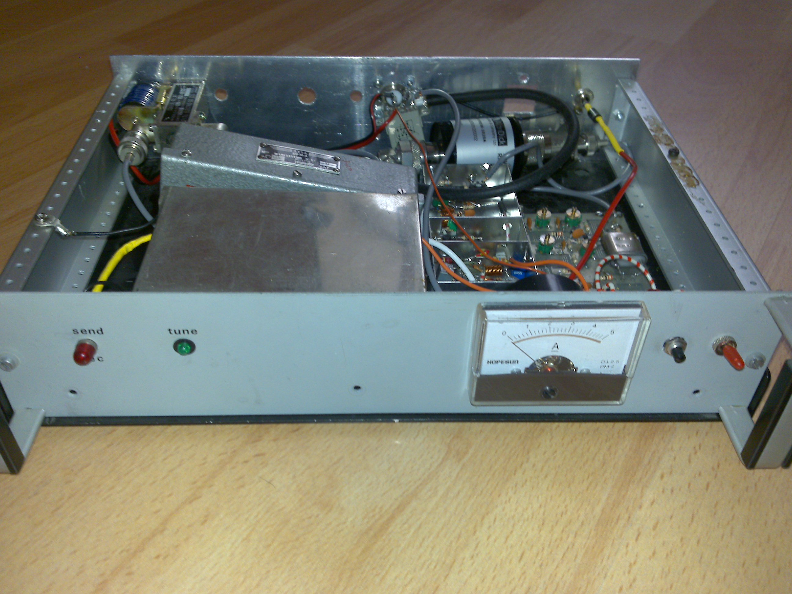
The transverter with the old relais and just some BNC connectors for measuring the power and harmonics:


The 20dB attenuator is to put behind my HF transceiver (FT-100) which gives a minimum of 3 Watts RF output on the HF bands. This is needed for not over driving the transverter input.
The next step is to make a simple half wave dipole for the first RX testing .... as we are not allowed to transmit yet in The Netherlands ......except on a dummyload.
I am also looking for a better amplifier part as 7 Watts is not much. I have seen easy power modules as the RA30H0608M which give 25 Watts on 70 MHz.
On 2-9-2009 I placed a 41 MHz crystal as Local Oscillator instead of the 41.666 MHz version. This gives me a normal read-out on the HF rig. As 29+41=70.000 MHz.
The crystal was donated by Jos PA3ACJ. I also placed the parts in a other housing so I could fit in the coax relais and the lowpass filter.
On the front I placed a 5A-meter to watch the current. This is not needed, but it covers the hole which was there from an old project :-)

Now to really get to work: I had some time to test the transverter as I only optimized the RX part by ear and TX by power meter on max power output.
Oeps .....not a good performance as I found out. First of all the RX part. I put a 70MHz -127dBm signal into the RX input and the IF of 29MHz to the spectrum analyzer.
Indeed some better performance was made as I had not adjusted the trimmers from 50 MHz to 70 MHz. That was easy.
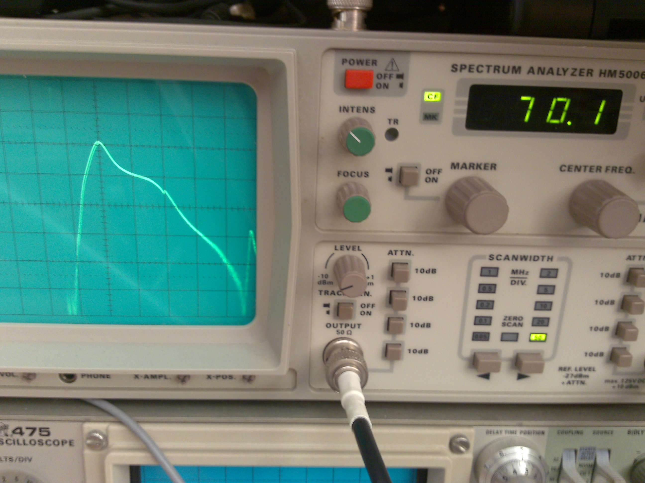
Now the TX performance. I put the output through a directional coupler as 7 Watts into a spectrum analyzer would destroy the input! What I saw was the following picture:

All the humps refer to harmonics on the carrier. The input was a CW signal and should result in a clean sinus wave form.
The best way to optimize was to take it step by step. Each part was decoupled and the output was measured per stage. All was well untill I came to the 2n3866 which had oscillation problems.
I changed some resistors for the bias current and all was quiet. See the next picture of the output. Now I had 300mW on 13 Volts. Turning up to 15Volts I could make 500mW.

The final stage PA with a BLW29 was connected and unfortunately no power was measured at the output. I had blown up the transistor in former testing as the collector current suddenly went up to over 3A .....
Today 8-9-2009 I will have to see if I have a spare BLW29 or if I have to purchase a Mitsubishi power module,
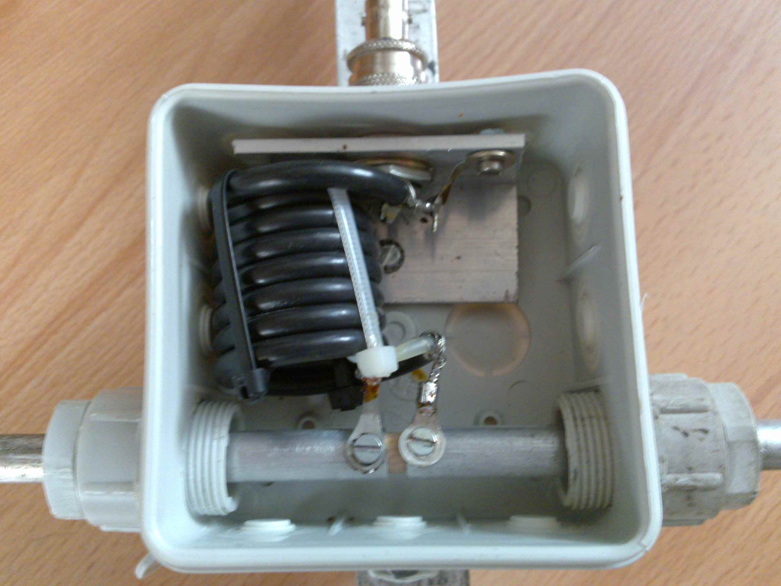
The antenna I made was a simple half wave dipole of 2x 104cm aluminium tube. To avoid RF current feedback I made a simple current balun by just turning a few loops of RG58 and placing it inside the plastic box. I had room for 8 turns, diameter 20mm.
The build of a 70 MHz lineair power amplifier
As described before, the BLW29 was destroyed and I searched for other transistors to make a new power amplifier.
I found the 2n5641 and 2n5643. Searching for datasheets on the internet I found out that they both run on 28 Volts. The 2n5641 gives around 6 Watts depending on the input power and the 2n5643 gives a max. of 60 Watts. This on 175 MHz.
As I have a power supply for 24 Volts I will not be tempted to drive these transistors to their maximum limits. Seen I will use them on a lower frequency they will probably have more gain on the lower voltage.
For using power transistors in Class-A SSB mode, you will need to make a bias voltage. On the website of YU1AW there are notes how to do this.
I have done the same with commercial build amplifiers on 430 MHz and workes fine. (see UHF amplifier page)
YU1AW gives examples of input and output coils for different transistors on 50 and 144 MHz. As I have made filters for 70 MHz I found out that for example a coil of 4 turns diameter 12mm tune fine in this band, but do not match the YU1AW values.
To make sure I will build the right stuff, I mailed YU1AW to verify and ask for his opinion on how to build a 70 MHz PA and why values of coils differ per type of transistor or Mosfet.
YU1AW gave some input to my questions; the transistors I want to use are not used in SSB mode but specified for FM use. By running them on 24V in stead of 28V as mentioned in the datasheet they will become more unlineair.
Difference in L1 and L2 coil values are due to transistor parameters / impedance. This will be a question of testing.
On 17-9-2009 I started building a test amplifier. On the photo's you can see the print board made by cutting away some copper.
I started with the first stage 2n5641and made a sweep via the spectrum analyser with the tracking generator.
The analyzer sweeps have been done without putting voltage on the amplifier board.
The signal from the sweep-output will leak through the componants and gives a good view of the DUT performance. No chance in damaging your analyzer input.
The highest peak was at 168 MHz and the coil and trimmer values had to be changed.
The analyzer picture is on X 50 MHz/Div and Y at 10dB/Div. At the analyzer input a 14dB attenuator for standard safety.
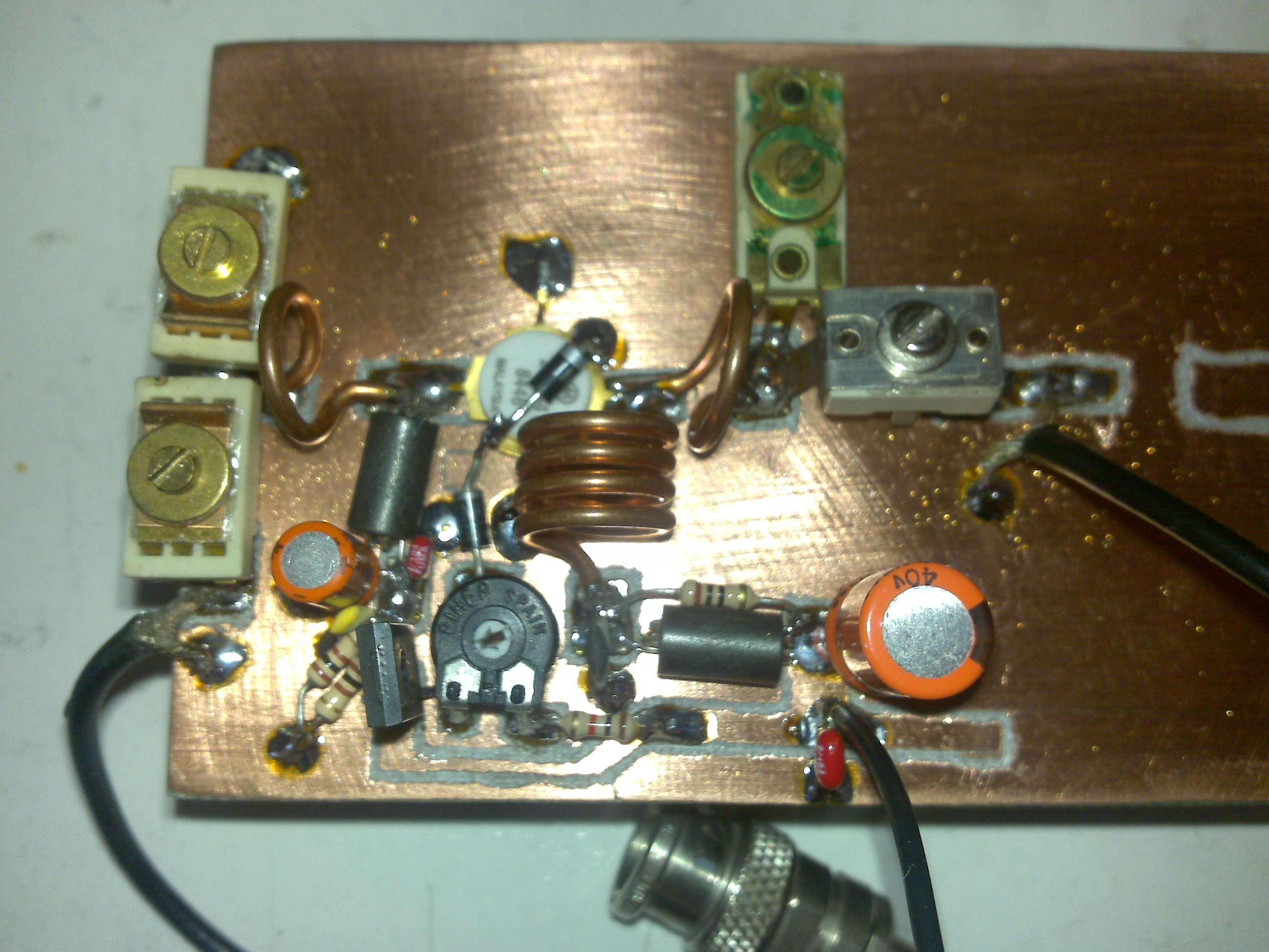

The coilL1 and L2 were 1 winding diameter 10mm. I changed them to 3 windings 12 mm diameter and it tuned to 70 MHz.
The input power from the signal generator was 20mW (13dBm) and output on the power meter was 400mW (26dBm), so the @ gain was 13dB which is a factor of x20.
After putting some extra 47pF ceramic capacitors parallel to the trimmers which were at maximum capacity (turned fully in) the output power of stage 1 went up to 460mW. Trimmers used are Arco type.
The coil change to 3 windings gave the following result:
Then I made the second 2n5643 stage:


The second stage sweep over 500 MHz span on picture 1 and now picture 2 with the lowpassfilter behind it:


Sweep of the total amplifier stage 1+2:

I need to buy a good piece of aluminium for cooling the transistors, at max power things will get hot for sure.
On 7-10-2009 I tested the total amplifier. The first stage pulled 200mA which was absolutely too much, without applying input power. This at 12V only. I made about 3 Watts.
Turning up the voltage gave 5 Watts, but bias current went up as well and by reaching 24V the transistor broke down.
I found out that the BD135 for the bias current was defect and that failed the circuit.
The second stage was tested (first stage omitted) and with 300mW input only a few Watts output was achieved. Grrr .... I took some time to test different componants. Extra capacitors by the trimmers and different coil values were used.
The final result is in the next picture. The whole amplifier gives exactly 15 Watts, at 340mW input by 12,5 Volts. This is conform datasheet specs.
The maximum voltage of 28V was not used yet as the 2nd stage transistor broke down at 26V. I put a 10k resistor in the BD135 collector to reduce the bias current and at 20V I achieved 20 Watts output. I had no guts to push the limit yet.

On 9-11-2009 I made another version of the amplifier with a BFQ34 and a BLF147, unmarked version. The output was 60 Watts without oscillations. Running on 26V and abt. 2,5 Amps of current.

If you like what you read on this site or have questions, please feel free to drop me an email via: pa3fxo at hotmail.com
17-09-2009 by PA3FXO
Home