SIMPLE FREQUENCY COUNTER WITH 8 LEDS DISPLAY
(1997)
NEDERLANDS ARTIKEL BENELUX QRP CLUB
Why simple?
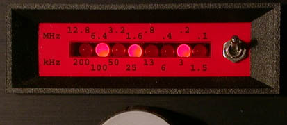
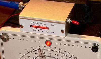
200 kHz - 100 kHz - 50 kHz - 25 kHz - 12.5 kHz - 6.25 kHz - 3.125 kHz - 1.5625 kHz.
As this is a little difficult to add, the figures are rounded off to the following values:200 kHz - 100 kHz - 50 kHz - 25 kHz - 13 kHz - 6 kHz - 3 kHz - 1.5 kHz.
Example: Leds D7, D5, D3 and D0 are on: 200 + 50 + 13+1.5 = 264.5 kHz.12.8 MHz - 6.4 MHz - 3.2 MHz - 1.6 MHz - 0.8 MHz - 0.4 MHz - 0.2 MHz - 0.1 MHz.
But mostly you do not need the switch. If you have for example a QRP transceiver for 10.1 to 10.15 MHz then you do use only the kHz position and you can see that you have to add 10 MHz to the kHz frequencies:
Working principle
The 74HC4060 oscillator with the 6.4 MHz X-tal generates a frequency of 390.625Hz in the kHz
position of the switch and 25 kHz in the MHz position. Only half the period is used for counting.
During the +5V half period, the 74HC4040 is reset. As soon as the clock pulse goes to zero,
the 74HC4040 starts counting the pulses from the BF494 preamplifier until the clock pulse
rises again to +5V. Then it is reset again. But just before the reset, the actual count
value is latched in the 74HC374, that also drives the output leds.
And that is all...
Modification for cases where the VFO works at half the working frequency
Sometimes a Poljakov diode mixer is used in direct conversion receivers. With such a mixer,
the VFO oscillates at half the reception frequency.
In those cases, add an RC network (100 pF / 4k7) in the CLK/RST line to the pins 11 of the IC's.
The RST/CLK pulse is now only a very short needle puls instead of half a period of the 390.625 Hz
signal and the counting period is doubled (minus the very short almost negiglible RST/CLK pulse).
As the counting period is doubled, the frequency read out is correct when the VFO oscillates
at half the working frequency.
If necessary, the error caused by the short RST/CLK pulse can be corrected by re-adjustment
of the 40 pF trimmer (adjust the frequency of the crystal oscillator a little lower than 6.4 MHz).
However, for the MHz position, you will have a considerable error as the reset pulse is quite long compared
with the short gate pulse in the MHz position.
Sensitivity
| Frequency (MHz) |
Sensitivity (mV rms) |
|
0.1 0.3 1 3 10 30 50 |
150 50 15 8 15 130 ? |
Notes
You should build the counter in a screened box to avoid RF interference in your receiver!!
Circuit diagram
big diagram
In my 80-40-30-20 M CW transceiver (3560,5 kHz)
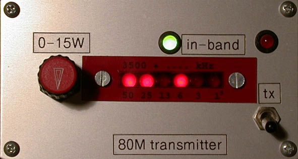
3581 kHz, led D7 is not used, green led D6 is the in-band led (3500-3600 kHz)
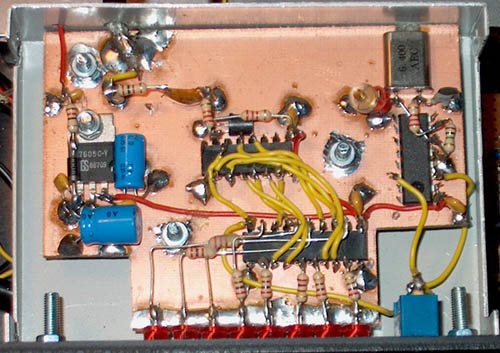
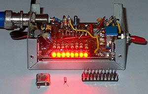
Inside one of the counters
FROM 3 TO 2 CHIPS!
(2004)
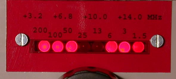
The little 2 chip version with 3mm low current leds.
Much more accurate than the old dial!
It is possible to connect the leds directly to the 74HC4040 and delete the 74HC374. It works as follows: We reset the 74HC4040, then count, then stop counting and display the frequency and then reset again etc. However we need a gating mechanism for the input signal for that. And for that gating we need again a 3rd chip! But Hans had a solution for that: Do not use a chip but a simple device like a diode that is switched on and off! Here is chosen for switching the supply voltage of the RF preamplifier. The input signal is only fed to the 74HC4040 when the RF preamplifier is supplied by the +5V of the gating signal. During the 0V period, the RF preamplifier is switched off and the 74HC4040 stops counting. The outputs do not change anymore and the leds are illuminated. The leds on their turn are only illuminated if the gating signal is zero and are off when the 74HC4040 is counting (gating signal +5V). At the beginning of the counting period, the 74HC4040 is reset by the short reset pulse from the 100 pF/470 ohm differential network.
Circuit diagram
big diagram
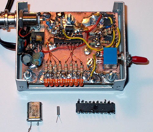
The prototype of the 2 chip frequency counter and the deleted 74HC374.
Compare the size of the small 100 kHz crystal with the 6.4 MHz one!
Despite the high serial resistors, the low-current leds are bright enough!
On off switch.
The RF preamplifier is switched on and off by the gating signal. Due to the varying load, this may cause
variations of the VFO frequency in the rhythm of the gating signal. A solution is a buffer amplifier or an on/off switch!
Switch on the frequency counter only when you want to read the frequency. Also the generated RF interference is not
a problem anymore! And it will also decrease the average current to less than 1% or less than 100 uA!
Sensitivity and accuracy.
The displayed frequency is a little dependent on the input level of the signal. This is caused by the settling time of
the RF amplifier. It is the price we have to pay for deleting one chip...
The following values were displayed as exactly 30 MHz:
100 mV: 30.0016 MHz
300 mV: 30.0009 MHz
1000 mV: 29.9999 MHz
The following values were displayed as exactly 10 MHz:
30 mV: 10.0006 MHz
100 mV: 10.0003 MHz
300 mV: 10.0000 MHz
In the MHz position, the difference at 30 MHz was 20 to 70 kHz, but this is not important. The MHz position is only used
to find the approximate frequency.
| Frequency (MHz) | Sensitivity (mV rms) |
|
0.1 0.3 1 3 10 30 50 60 80 100 |
500 200 50 30 30 100 200 300 500 1000 |