FOUR BAND CW TRANSCEIVER
(1999)
KLIK HIER VOOR DE NEDERLANDSE VERSIE
Four band CW transceiver with direct conversion receiver with sideband suppression.
Four band version of the 80 meter CW trx with dc receiver with sideband suppression
Restoration of my old three band CW transceiver with direct conversion receiver
The three band CW transceiver constructed in the beginning of my radio amateur carreer was my most used transceiver in that period.
But it had a lot of disadvantages. No 30 meter band, some frequency drift, no accurate frequency read out, a double side band direct conversion receiver, spurious emissions did not comply with the current limits. There were a lot of problems with 50 Hz hum due to the audio transformers and 88 mH inductances in the filters. Therefore, it was time for a restoration. I decided to dismount all the old printed circuit boards and keep them as a memory. Only the enclosure
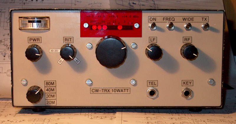
is used again, the damaged paint due to the intensive use in the shack and mobile while sailing is left in original state. It should become a four band version of the 80 meter band CW transceiver with the phase method used in the receiver. Adding the 30 meter band and also a simple frequency counter were the most important wishes.
Well, it became a success! Side band suppression is good. The four band transceiver is again my most used transceiver.
Details of the transceiver with single side band direct conversion receiver
Please read the page about the 80 meter band version for the details about the phase method and side band suppression.
Only the differences between the four band version compared with the 80 meter version will be discussed here.

Unique simple construction without PCB! The solidity is tested with my toes!
The 4 band transceiver with single side band direct conversion receiver
Block diagram of the tranceiver
THE RF PART OF THE DIRECT CONVERSION RECEIVER
RF part of the receiver
Preselector, RF preamplifier and RF phase shift networks
At the input, you will find the very standard and useful RF attenuator. Bandswitching is done by the diodes 1N4148. One diode conducts, the others are blocked and have a high negative blocking voltage of 12 volt. There is one preselector plus RF preamplifier per band. This was easier than one RF amplifier with switching circuits. After the preamplifiers we have the 45 degrees RF phase shift filters. It are simple RC networks, all tuned with the trimmers for approximately plus and minus 45 degrees phase shift. They also compensate for amplitude differences. Adjust them by ear, try different trimmer settings while adjusting the other while listening to a signal on the suppressed side band at centre frequency of that CW band. For the best settings for amplitude, it is possible that one network is plus 55 degrees, the other minus 35 degrees, but the difference should be 90 degrees.
Mixers and LF preamplifiers
The plus and minus 45 degrees phase shifted signals are mixed to LF frequencies by two mixers. These mixers are CMOS switches of a 74HC4066, very cheap and performance is good. Adjust the 5k potentiometer for minimum audio detection of strong broadcast stations.
The mixers are followed by two audio preamplifiers with transistors. They perform better than the op-amps in the first version of the four band transceiver.
AUDIO CIRCUIT AND SIMPLE FREQUENCY COUNTER
Audio and frequency counter
LF circuit
The LF phase shift networks and CW filter are the same as that of the 80 meter version. Three potentiometers of 500 ohm are added to have the possibility of fine tuning (narrower or wider) of the CW filter. Low noise TL072 op-amps are used instead of the LM358. The LF switch is replaced by a volume potentiometer. The volume circuit is unusual, but in this way the gain of the LF amplifier decreases at lower volume settings. The advantage is that also the noise of the audio amplifier decreases. The diodes 1N4007 are added in the supply connection of the LM386 to lower the voltage with 1.4 volt. The maximum voltage of the LM386 is not exceeded when the supply voltage of the transceiver is 13.6 volt.
Simple frequency counter
The simple frequency counter is described somewhere else at this website and is also used in the 80 meter version of the transceiver. Eight leds are used to display the frequency, but when tuned to the desired band, only six are used.D7 and D6 are only used for tuning to the desired CW band:
For 80 meter, led D6 and D7 are always on.
For 40 meter, led D6 is off, D7 is on.
For 30 meters, D7 and D5 are off, D6 is on.
For 20 meters, D7 and D6 are off.
So only six are used to read the frequency within the band (five for 30 meters). Just add the values of the burning leds.
THE VFO PLUS RIT
Circuit diagram of the VFO
VFO
In the heterodyne VFO, two signals are mixed in a NE612 mixer. One of the signals is from the variable oscillator with a frequency range of 4.432 to 4.032 MHz. The other is from a crystal oscillator. For 10 MHz, the crystal frequency is 14.318 MHz, giving a frequency range from 9.886 to 10.286 MHz. For the other bands the cheap-crystal frequency is 18.432 MHz. This gives a frequency range of 14.0 to 14.4 MHz. This frequency is divided by two for 7 MHz and by four for 3.5 MHz.
There is also a temperature compensation circuit with the NTC. It is adjusted with the 10 k potentiometer while tuned at center frequency. I did that by measuring the frequency in the evening when the room temperature was 21 C and in the morning at 15 C. The frequency drift was considerably improved by this circuit.
The switch S3 is switched on for a smaller tuning range (CW band only) on the higher bands.
The VFO coil is wound on a T50-2 toroide. The coils in the bandfilters for 10 and 14 MHz are wound on 6mm cores. Adjust them for maximum output signal at the emitter of the BF494.
RIT
The RIT is activated by a CMOS switch of the 74HC4066 IC that also contains the two switches for the mixers. In the lowest position (pos 0), the VFO frequency is the same as the transmit frequency. Tune zero beat with a signal, then rotate the RIT potentiometer to the desired audio beat and mark it for that band.
The FSK input is never used, just delete it together with the transistor.
Mistake
The first version of the heterodyne VFO used a variable frequency of 4.0 MHz to 4.4 MHz and crystals of 6 MHz and 10 MHz for the 10 MHz and 14 MHz bands. This was a very bad choice, especcially for 30 meters. The frequencies of the variable oscillator (4.0 MHz to 4.4 MHz) and the crystal oscillator (6 MHz) are too close to each other. The difference of these signals, 1.6 MHz to 2 MHz caused a lot of spurious signals in the receiver and the transmitter. For a good heterodyne VFO, one frequency should always be higher than the final frequency or at least much higher than the other input frequency of the mixer.
THE 10 WATT CW TRANSMITTER
Diagram of the transmitter
The transmitter explained
1st driver stage
With the 1k potentiometer, the output power can be adjusted from 0 to 10 watts. After this potentiometer, the signal is amplified by a BF494 transistor. This driver is switched by the morse key via the BC557 transistor. The diode and 1 uF capacitor are added for a correct shape of the CW signal.
2nd driver stage
The second driver is a 2N4427 transistor. The 2x2200 ohm resistors provide for RF feedback and DC voltage at the base of the
driver transistor. The 2x10 ohm emitter resistors are a kind of limiter to prevent overdrive of the stage.
Final RF amplifier
Of course you should not use such an expensive VHF transistor but for example a 2SC1969. I had two MRF238 transistors unused in the junkbox, so why not.
The 2x 12 ohm at the base create a low input impedance, important for a good stability. The 220 pF capacitors have a low impedance for higher frequencies, they do prevent HF and VHF oscillations. And finally, the 2x 100 ohm resistors with the 2x 0.1 uF capacitors are a negative feedback circuit that prevent oscillations at frequencies below 1 MHz.
The output filters are wound on T50-2 and T50-6 cores. The number of windings is adjusted by checking the resonance frequency with a known capacitor (100 pF or so) and a dip meter.
Antenna switch
When in non-transmit mode, for maximum performance, the diodes are shortened by a switch to avoid any intermodulation problems. When in transmit mode, the antenna switch operates in break-in mode. The diodes are conducting when key-up and blocking if key down.
Notes
Built via the ugly method (dead bug method). Parts are soldered at one side of he double sided unetched print.
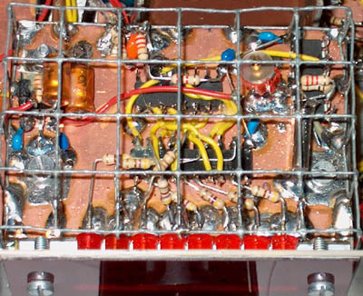
The VFO has to be placed in a screened enclosure. The frequency counter is also screened with chicken wire.... The advantage is that you can make some modification or adjustments through the holes of the chicken wire.
Inductances are commercially available types looking like big resistors. Lx are wired 6 hole cores.
Do not use a 74HCT type but a 74HC type for the IC's!
Performance
Sensitivity:
80 meter: -120 dBm
40 meter: -122 dBm
30 meter: -120 dBm
20 meter: -118 dBm
AM dynamic range:
80 meter: 95 dB (very good)
40 meter: 87 dB (good)
30 meter: 92 dB (good)
20 meter: 83 dB (acceptable)
Side band suppression:
80 meter: 40 dB
40 meter: 41 dB
30 meter: 43 dB
20 meter: 38 dB
Transmit power:
Max. 10 W at 13.5 V
Suppression of harmonics:
Better than 45 dB, above 30 MHz better than 60 dB.
After restoration, it is a good transceiver for CW! Sometimes weak AM detection of very strong broadcast stations is heard but that disappears with some RF attenuation. My conclusion is that the phasing method for suppression of a side band is also suitable for a relative simple and uncomplicated transceiver with direct conversion receiver for the 40, 30 and 20 meter band.
PHOTOGRAPHS
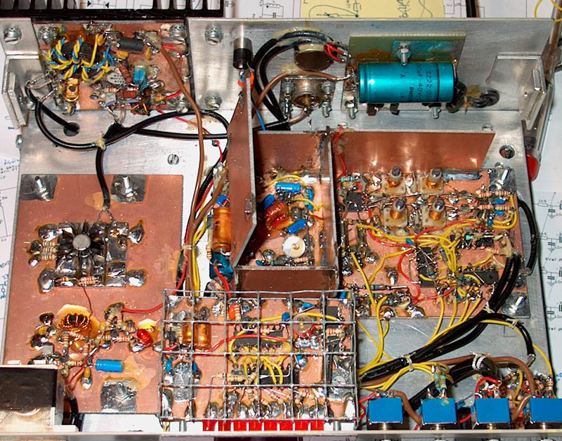
Frequency counter, VFO, PA Driver and PA
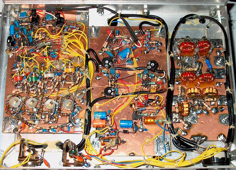
Direct conversion receiver with sideband suppression, phasing networks, PA antenna filters.
The frequency counter with 8 leds, only 3 IC's and it's own 5 volt stabilizer.