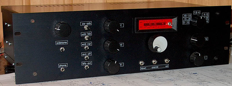
This simple homemade RX gives me much more fun than a much better commercial receiver!
MY FIRST (HOMEMADE) SHORTWAVE RECEIVER
10 kHz - 30 MHz
(1997)
This simple homemade RX gives me much more fun than a much better commercial receiver!
As I did not have a shortwave receiver anymore, that would be a nice project to try out how it is to work with
"dead bug" construction on unetched PCB.
For the housing of the receiver I bought a standard 19 inch cabinet and found a way to make good looking text labels
on it with a label printer and the window function.
Did I like the construction?
The "dead bug" construction method on unetched PCB was a very nice method to make a prototype, also useable
as the final version. Use of a standard housing with text labels is a very easy and fast method to make a nice enclosure.
And the receiver?
It is a big but not so very complex and stable receiver, used almost daily to receive all kinds of signals such as
28 MHz beacons, amateurs, the clubstation, ships, new 5 MHz amateur bands in the UK, 518 kHz Navtex, DCF77 time signal
decoding at 77.5 kHz. It is stable enough to receive all kinds of digital modes.
Recently modified
However, a second shortwave receiver was made, simpler, smaller and with a better VFO stabilizer circuit. Due to the unique
construction method it was quite easy to make modifications and improve the VFO and AVC circuit of this receiver
as a result of the experiences with the new shortwave receiver.
Block diagram.
The VFO
The VFO.
big diagram
(VCO frequency) x (frequency variation of the VXO) / (VXO frequency)
So the actual frequency band that can be tuned by the 10 turn potentiometer is depending on the VCO frequency and the frequency variation of the VXO .
The VFO coil
The coil is wound on a piece of a plastic potentiometer axis. It is totally glued in plastic with a glue gun to avoid
all kinds of noises when knocking against the enclosure of the receiver. How funny it was to see that the VFO stayed
exactly on frequency while the hot plastic of the glue gun was cooling off!!! Normally my VFO's start drifting already
at the slightest temperature changes....
Up-down switches.
One important remark about that: The Up switch does only work properly if the VXO is tuned to a high frequency.
For the lower VCO frequencies it works already when the VXO is tuned to its center frequency.
And for the Down switch it is just the opposite.
Sometimes a (not very stable) locking occurs while there is an AC ripple on the loop (check with an oscilloscope on TP2).
But you can solve this problem with some DC offset, adjust the 10k potentiometer a little to get this DC offset.
The RF part

The RF part.
big diagram
The mixer
The mixer is a Winner! The SL6440 is very good. During tests of the prototype, 5 meters of wire was connected
directly to the input of the mixer without any preselection and many 80 meter amateur stations could be received
without any overload or intermodulation products!
The IF and BFO
A 5 pole IF ladder filter (3.5 kHz wide but I will retune it to 2.4 kHz soon) is followed by a NE612 BFO mixer.
So there is no IF amplifier! I did spent a lot of time to try to make a VXO with an overtone crystal at 48 MHz,
but without success.... That is why the BFO works at 16 MHz and is tripled to 48 MHz. The LC circuit in the
collector is already tuned to 48 MHz. So the second transistor is not a tripler but an amplifier.
The IF gain control is not really an IF control as it is in the LF part of the receiver.
But it has the same effect: Control the AVC voltage.
The LF part

The audio part.
big diagram
The Frequency counter
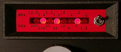
Frequency counter with 8 leds.
The Frequency Counter and mixer VFO-BFO.
big diagram
200 kHz - 100 kHz - 50 kHz - 25 kHz - 13 kHz - 6 kHz - 3 kHz - 1.5 kHz.
Example: Leds D7, D5, D3 and D0 are on: 200 + 50 + 13+1.5 = 264.5 kHz.12.8 MHz - 6.4 MHz - 3.2 MHz - 1.6 MHz - 0.8 MHz - 0.4 MHz - 0.2 MHz - 0.1 MHz.
The MHz position is not so easy to use, but normally you will use it only to find the desired amateur band. Then you do use only the kHz position, reading the frequency is easy then.
The mixer for the Frequency counter
To get a signal equal to the reception frequency for the frequency counter, a mixer is used to mix the VFO and BFO
down to the reception frequency. The mixer is followed by a 30 MHz low pass filter. The VFO potentiometer is set to
maximum in my version, the potentiometer connected to the 48 MHz is set to a compromise between output signal and spurious.
If the spurious is too high, the frequency counter does display random frequencies.
PHOTOGRAPHS
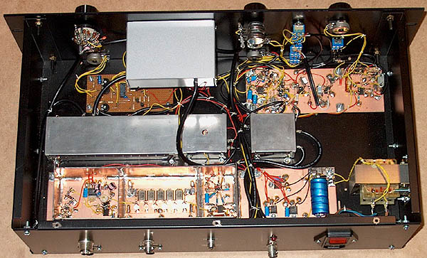
Interior of the receiver.

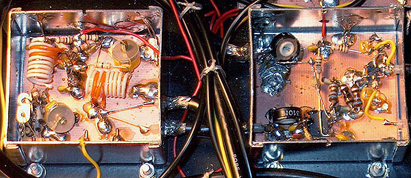
VFO 48 - 78 MHz with stabilizer.

RF part with 48 MHz crystal ladder filter.
BFO 48 MHz and mixer VFO-BFO for frequency counter.
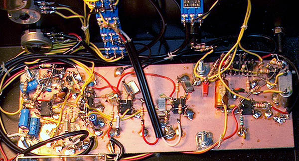
LF part with CW filters and side tone oscillator 700 Hz.
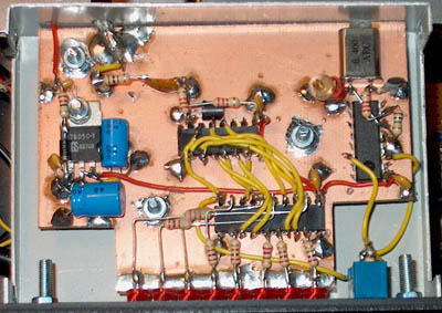
The simple frequency counter with 8 leds.
Results
It is a nice receiver with a pleasant sound. Due to the very good SL6440 mixer, the 3rd IP is approximately +8 dBm, strong signals are not really a problem! The narrow CW filter is very good for the suppression of broadband and narrow band interference. Of course it does not have all the features of a good commercial receiver, there is for example no Noise Blanker or Notch filter. But I had a lot of fun with this receiver, know how it works, can repair everything, it is easy to make modifications and finally, the second output of the mixer for the counter can be used as a signal generator from 0 to 30 MHz (but it is not spurious free enough for a transmitter as it was intended for!).