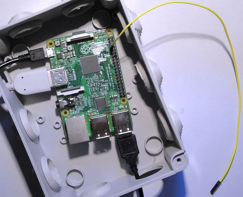
The Raspberry Pi in use as RF generator.
The yellow antenna wire is connected to the RF output GPIO_4 pin 7.
RF GENERATOR WITH
THE RASPBERRY PI
2017
KLIK HIER VOOR DE NEDERLANDSE VERSIE
The Raspberry Pi in use as RF generator.
The yellow antenna wire is connected to the RF output GPIO_4 pin 7.
Example for 1 MHz, with +39.4 parts per million correction :
freq_pi -f 100000000 -y 39.4
Example for a sweep from 1 MHz to 100 MHz step 1 MHz with 100 ms delay between steps:
freq_pi -b 1000000 -e 100000000 -i 1000000 -d 100000
Typing "command lines" in a terminal window is not really convenient. But it was not very difficult to make a simple GUI in Python. Jenny List G7CKF had made a similar program that I could use as an example. You can press buttons with the mouse and the program makes the correct "command lines" and sends it to the nice program of Jan Panteltje. This program was also modified a bit, so that you can make an FM or AM modulated burst of 20 seconds.
Installation
Create a new directory and copy the files in the following ZIP file to that directory:
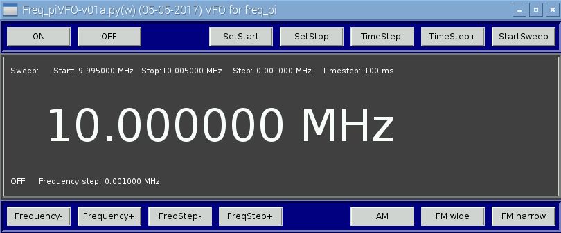
The Graphical User Interface that makes it easier to give the commands.
SetStart & SetStop
Set the start- and stopfrequency of the sweep to the tuning frequency.
TimeStep- & TimeStep+
Set the time step of the sweep per frequency step, so it determines the sweep speed.
StartSweep
Starts the sweep.
Frequency- & Frequency+
Tuning.
FreqStep- & FreqStep+
Set the frequency stepsize of the tuning and also of the sweep.
AM & FM wide & FM narrow
Gives a modulated RF burst with a length of 20 seconds. After 20 seconds, the signal stops and you have to press the button again.
Measurements of the audio characteristics of receivers
Connect the audio output of the receiver with the soundcard of a PC with an audio spectrum analyser program.
For example: 11sa.htm
Program the frequency sweep as follows:
Start frequency at zero beat with the receiver (0 Hz audio tone)
Stopf requency: Startfrequency plus the audio range you want to measure.
Frequency step: 10 Hz
Time step: 100ms
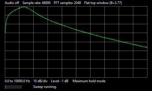
Set the trace of the audio spectrum program to Max Hold and start the sweep, the trace will be drawn on the screen as shown below. If you want to compare two measurements, save the first measurement into the trace memory. Below you can see the wide bandwidth green colored. The orange colored narrow bandwidth has been measured first and is stored in the trace memory.
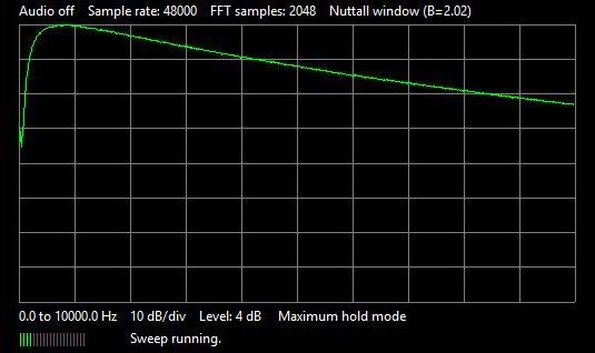 Audio characteristic of the regenerative receiver with tubes |
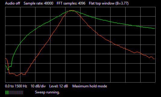 Audio characteristic of the 80 meter CW transceiver Green: Wide band CW characteristic Orange: Narrow band CW characteristic |
Measurements of the receiver for QRSS signals (weak slow-peed Morse code)
This measurement is equivalent to the "Receiver Audio Characteristics Measurements" as described above. When measuring the unwanted low sideband, the stop frequency is set to zero beat with the receiver (0 Hz audio tone) and the start frequency equal to the stop frequency minus the audio range you want to measure. The desired sideband is the orange trace, the unwanted one is the green trace. The sideband suppression is the difference between both traces. The peak of the desired orange sideband and the unwanted green sideband dip should lie at the position of the red arrow. Could be better!
 Bandwidth of the QRSS receiver |
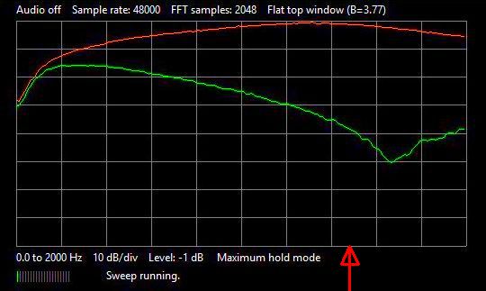 Sideband suppression of the QRSS receiver |
Adjustment of the AM suppression of a direct conversion receiver
From the 30 meter QRP transceiver, the 500 ohm potentiometer in the receiving section has to be adjusted to maximum suppression of the detection of strong AM signals in the nearby broadcast band. The RF generator is AM modulated and tuned to a frequency in the middle of this band. The level is adjusted (positioning and adjusting the length of the antenna) that a clear signal is heard. Then the potentiometer is adjusted so that this signal is minimally audible.
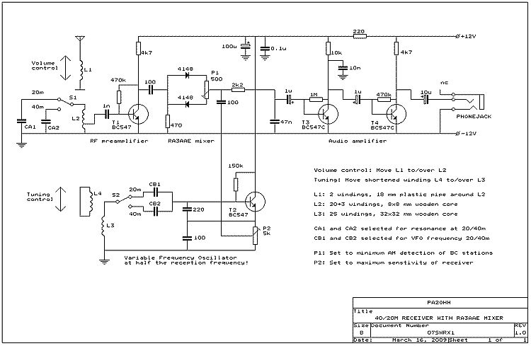
The 500 ohm potentiometer of the direct conversion receiver has to be adjusted to maximum AM suppression.
Measurement of the sideband suppression of the 80 meter CW transceiver
Tune the RF generator to the desired sideband and measure the level. Then tune the RF generator to the unwanted sideband and measure the level again. The difference is the sideband suppression. It was exciting to measure that side band repression. Because 20 years ago, the receiver had to be adjusted quite accurately for a sideband suppression better than 40 dB. And ... After 20 years of use, it was still 41 dB!
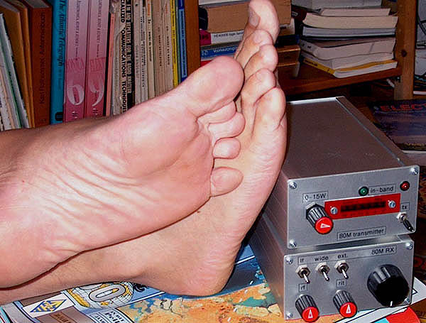
How is the sideband suppression of the direct conversion receiver after 20 years of use?
SOFTWARE
Required Python version:
Changes to the program freq_pi_oh1.c
For the Raspberry Pi version 2b, a variable PLL0_FREQUENCY has to be changed to 1000000000.0 Hz. This can be done with the Geany editor with basic features of an integrated development environment. This variable was previously modified for other versions. If you want to change something yourself, do not forget to compile the program again!
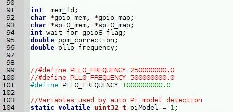
Changes to the program freq_pi_oh1.c can be done with the editor Geany
with basic features of an integrated development environment.

The added code to generate an FM or AM burst.