SIMPLE 10 MHZ GPS FREQUENCY
STANDARD AND RF GENERATOR
(2017)
The simple GPS frequency standard and RF generator.
Simple GPS frequency standard and RF generator
My first frequency standard is built up around a GPS receiver module, model NEO-6M, type NEO-6M-0-001 of the company "u-blox AG". The disadvantage is however that it can generate a maximum reference frequency of 1 kHz. But this new GPS module model NEO-7M, type NEO-7M-0-000 can generate reference frequencies upto minimal 10 MHz with a resolution of 1 Hz! For example 10139991 Hz! And it goes even higher than 10 MHz at the expense of some extra jitter. Great, a real RF generator that can be adjusted in steps of 1 Hz and with an accuracy of minimal 2e-8! perfectly suited for all kinds of applications. Unfortunately, the signal is not clean enough to use it as a VFO for a transmitter or a receiver.
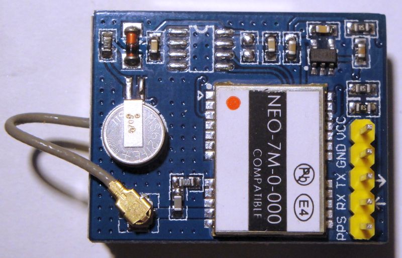
The GPS module model NEO-7M, type NEO-7M-0-000
Hardware
The module is built around a GPS receiver module, model NEO-7M, type NEO-7M-0-000 of the company "u-blox AG".
Ayoma Gayan Wijethunga had described in his blog how the GPS module can be connected to the Arduino Nano and how you can communicate then with your PC with the GPS module. A very simple program in the Arduino sends the commands from the PC to the GPS module and from the GPS module to the PC. And you can see them with the in the IDE integrated Arduino Serial Monitor. And also the programming of the time pulse is very simple and will be discussed later.
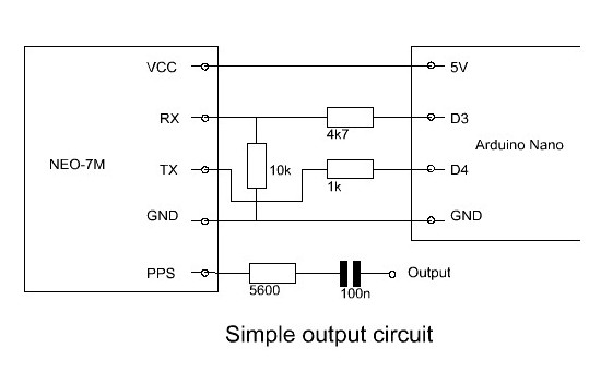
Diagram
The GPS receiver works with 3.3 volt levels and therefore there is an attenuator network with a resistor of 4,7k ohm and 10k ohms inserted between the 5 volt data output of the Arduino Nano and the RX input of the GSM module. The 3.3 volt TX output of the GSM module is just enough for the input of the Arduino Nano. I have added a 1k resistor between as security. When something goes wrong at the Arduino Nano side, it is almost sure that the GSM module will survive.
Of course, we can not connect the time pulse output (PPS pin of the GSM module) directly to all kinds of applications. A resistor of 5600 ohm and capacitor of 0,1 uF are added to avoid a short circuit and to eliminate the DC component. It is important that the resistor is connected directly to the pin and that the antenna does not see the wiring of the reference signal to the pin. Otherwise, the harmonics of the reference signal can disturb the reception of the GPS signal!
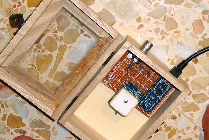
The whole is built in a wooden box for tea bags with a window in the lid, so that you can see the leds light up. The Arduino Nano, the 74HC00 and GPS module ares mounted on a piece of pertinax. The solder pins are made of cut-off wires. Bend them into a U-shape, insert them through two holes and twist the ends together.
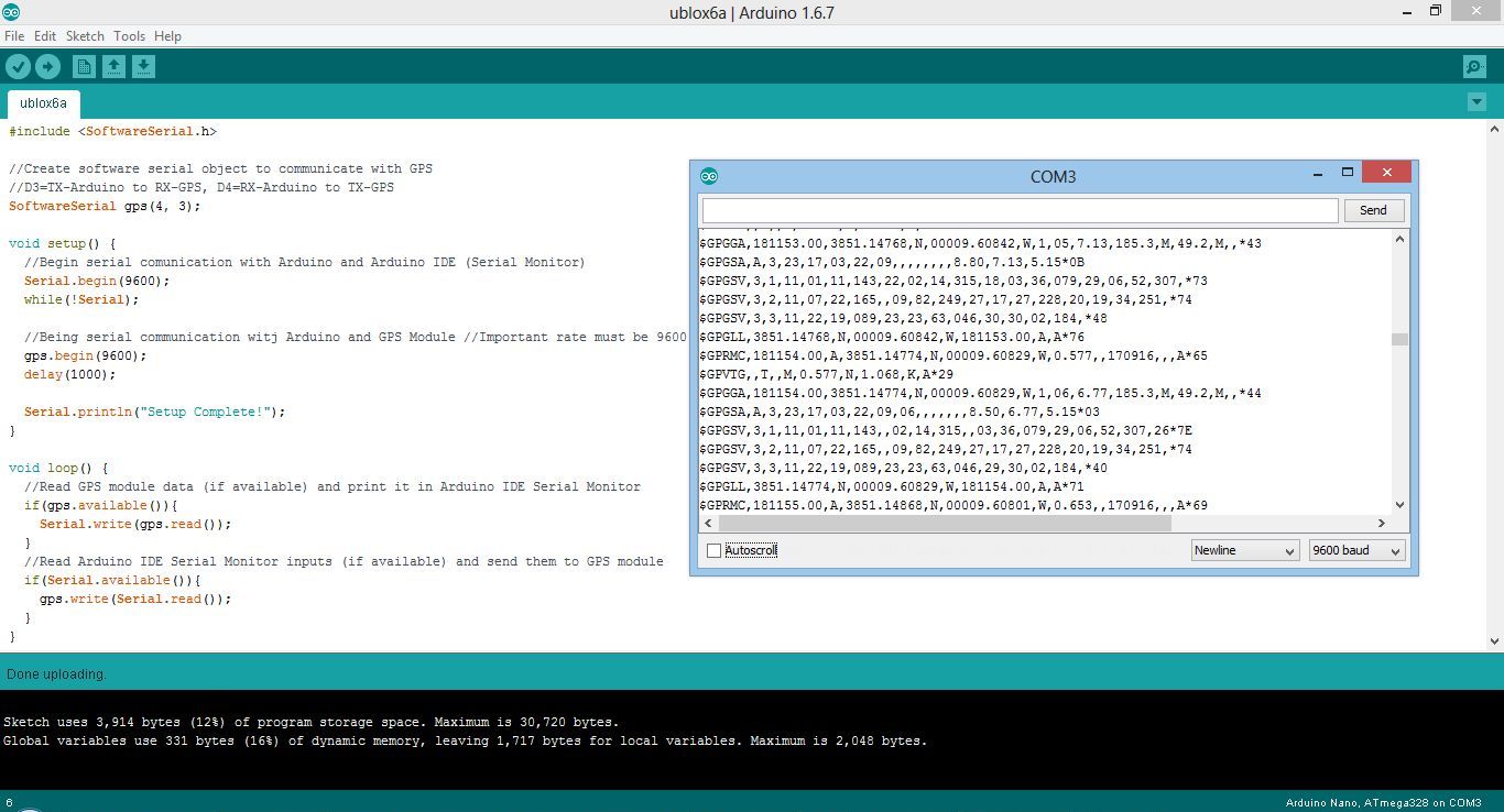
The developement environment (IDE or Integrated Developement Environment) of the Arduino.
Also the small Serial Monitor screen is visible with the data of the GPS module.
Software for Arduino Nano
Programming a micro controller has never been so easy, even a layman can learn it in a few minutes! You can find it at https://www.arduino.cc/ under downloads. And there is much more information about the various Arduino versions. I use the Arduino Nano.
Download and install the IDE. Connect the Arduino Nano with your USB port on your laptop and with "Tools - Port" you can select the correct COM port. When it works,
you have the correct COM port.
With "File - Open..." you can open a program, that is a file with the extension ".ino". With the first V on the toolbar, you can check if a program has errors. With the second round with an arrow you can compile the program, uploaded it and then you are ready!
A program consists of two parts. The "void setup ()" part contains the configuration, for example which ports are configured as input or output. The second part "void loop ()" contains the program. More information can be found on the above mentioned website of Arduino.
Type the following simple little program "ublox6a.ino" over and upload it by pressing the second round with arrow. Then choose "Tools - Serial Monitor" (not Serial Plotter!) And you will see the data from the GPS module appear on the monitor screen.
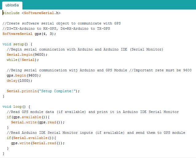
The simple program "ublox6a.ino" for the Arduino Nano.
CLICK HERE TO DOWNLOAD THE PROGRAM FOR THE ARDUINO
Software for GPS module
We have already programmed the Arduino Nano and connected it to the USB port of the computer. Shut down the IDE of Arduino Nano. The Arduino Nano is now working as an USB-UART device.
We use the "u-center software" which can be downloaded from the manufacturer's website: https://www.u-blox.com/en/product/u-center-windows. With the first choice on the toolbar, you can select the correct COM port. If you do that correctly, it will work. With the program you can see lots of things like the strength of the signal of the satellites, your position on Google Maps and what we want to use, programming time pulse!
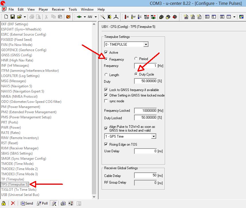
De "u-center software", the part with which we can configure the frequency.
For the NEO-6M module we did use "TP (Timepulse)" to program the reference frequency. But for the NEO-7M that does not work and we have to use "TP5 (Timepulse)". Activate "Frequency" en "Duty Cycle". You have to program two frequencies, one for when there is no fix. I programmed it for 1 Hz so that the led blinks if there is no fix. You reference frequency has to be programmed in the part "Frequency Locked". This can be any frequency you want till at least upto 10 MHz. My module did work till 16 MHz, but then you will have some jitter.
You can save the setting. This has to be done in the choices "BBR-0", that is the backup memory and in "3-I2C-EEPROM". Unfortunately, my module does not have a EEPROM and I have to reprogram it often when the backup battery is discharged.
Mark VK6WV had the following remark:
"When I save the configuration as your article suggested it did not save. After reading and re-reading the user guide I went to GNSS configuration under "Tools". I read the GNSS to a file after making sure TP5 had been set. Then I saved this same file back to the device with the "Store Configuration into BBR/Flash". This worked."
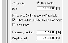
Setting to calibrate the QRSS receiver on 10140 kHz.
The 10th harmonic of the signal is used.
Use
Indoors, the GPS receiver has sometimes some difficulty to find a FIX. I use a power pack as is used for smartphones when playing Pokemon Go to feed the frequency standard and then go outside. When it has found the FIX, it will continue to work well when indoors.
The module in the wooden box radiates enough power to calibrate my receiver. The signal on 10140 kHz is even too strong and harmonics cause some interference to the GPS signal. For a real strong signal, you can connect a wire to the output connector. If you need a weaker signal to test your receiver, tune it to 1/2x the frequency (5070000 Hz in this example) and 25% duty cycle. For weaker signals use 50% duty cycle and an odd division (1/5, 1/7, 1/9 etc.). For the calibration of my QRSS receiver, I use a division of 1/10 with 25% duty cycle (1014000 Hz).
The used module is an outdated model, there are already newer ones. See https://www.u-blox.com/en/position-time.
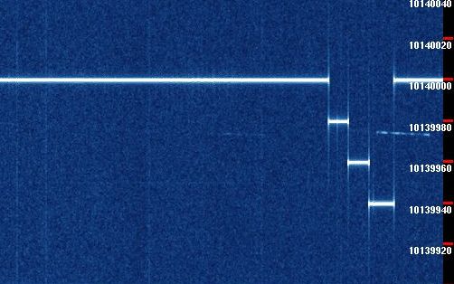
A perfect signal to calibrate the QRSS receiver on 10140 kHz.
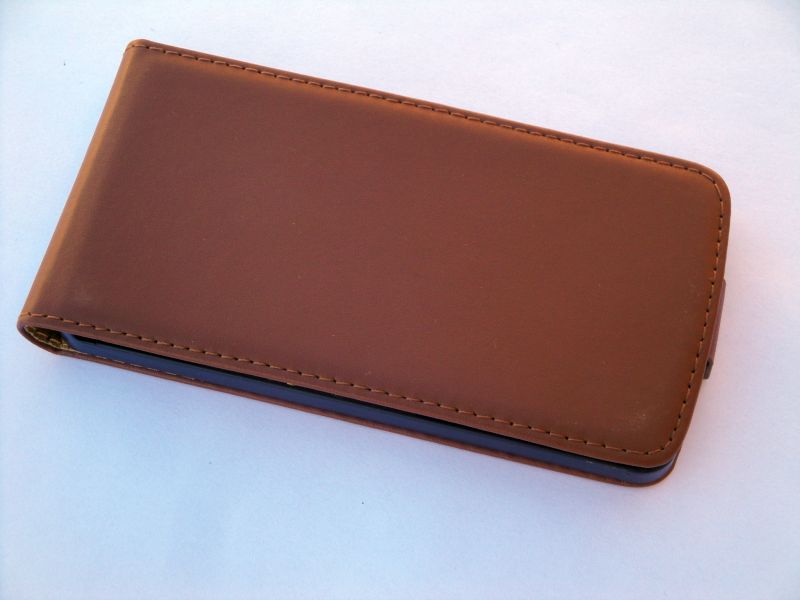
Another sample is built in a smartphone cover. Open it to use the frequency standard.
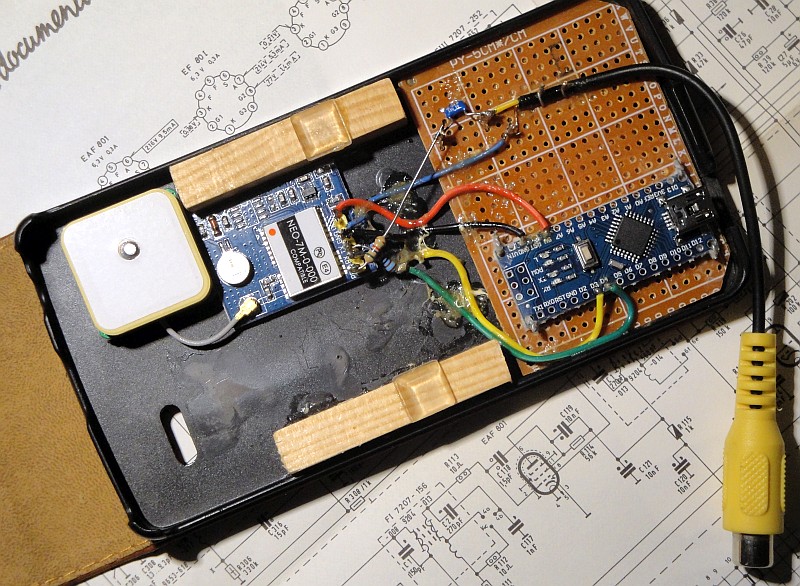
The antenna is placed further away from the module and pin with reference signal.
GPS clock and position
Modern web browsers like Google Chrome, Chromium, Firefox support the web Serial API. Connect the module to your USB port, press -START- and connect to the serial port of the module. The GPS data is decoded and used to make a clock. Also the position information can be used to calculate your QTH locator or open a link to Open Street Map.
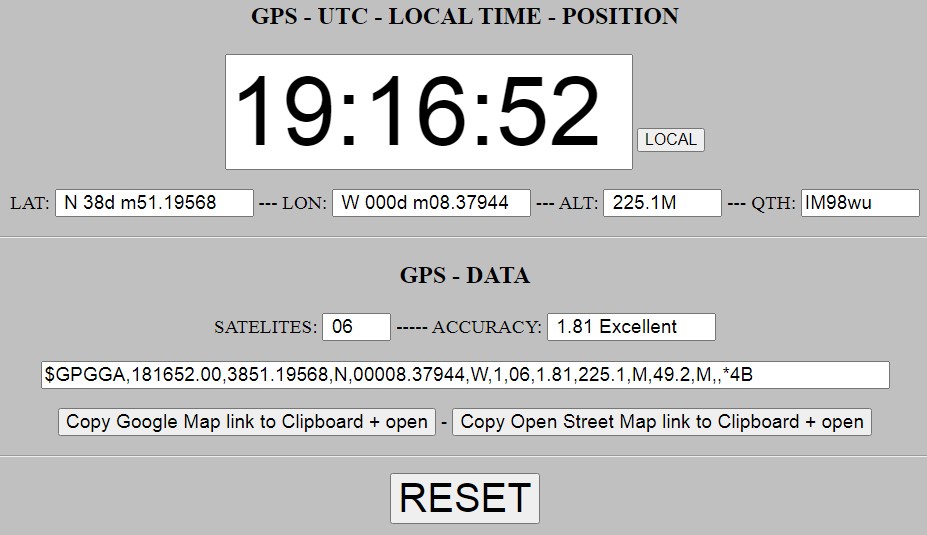
GPS clock and location information
CLICK HERE TO DOWNLOAD THE HTML FILE FOR THE GPS CLOCK
<
Index PA2OHH