EXCELLENT 30 METER RECEIVER FOR
LOW POWER QRSS BEACONS AND PSK31
(2011)
KLIK HIER VOOR DE NEDERLANDSE VERSIE
Reception of very low QRSS beacon transmitters
There is a group enthusiastic radio amateurs that is doing experiments with very low powers. That is possible by using a very slow CW speed. QRS mean reduce your CW speed. With that extra S of QRSS they want to indicate that it is really a very low CW speed. A dot lasts 6 seconds, a dash 18 seconds! Most of the activities take place in a band of only 300 Hz: 10139.8 to 10140.1 kHz in the 30 meters amateur band. The signals are so weak, that you cannot hear them. But you can see them on the monitor of the PC. The audio output of the receiver is connected to the sound card of the PC. With a special software program, you can make bandwidths of 0.3 Hz or even less and display the signals on the monitor.
The receiver suppresses the unwanted side band by means of the phase method. And a
crystal filter improves the selectivity and avoids overloading by strong broadcast transmitters.
Excellent receiver with side band suppression, crystal filter and modified antenna circuit
It was quite simple to modify the simple direct conversion receiver with the phase method to a single side band receiver. Two mixers were required instead of one and simple phase networks in the RF part and LF part. As the frequency band of 10140.0 MHz to 10140.1 MHz is only 100 Hz wide, we can use two very simple LF phase networks consisting of one capacitor and one resistor. That is an advantage, because there is not so much space in the plastic housing of the receiver. And the receiver has to be supplied with batteries, these networks do not require any current. A wide band 90 degrees phase networks with op-amps in the audio part was not possible.
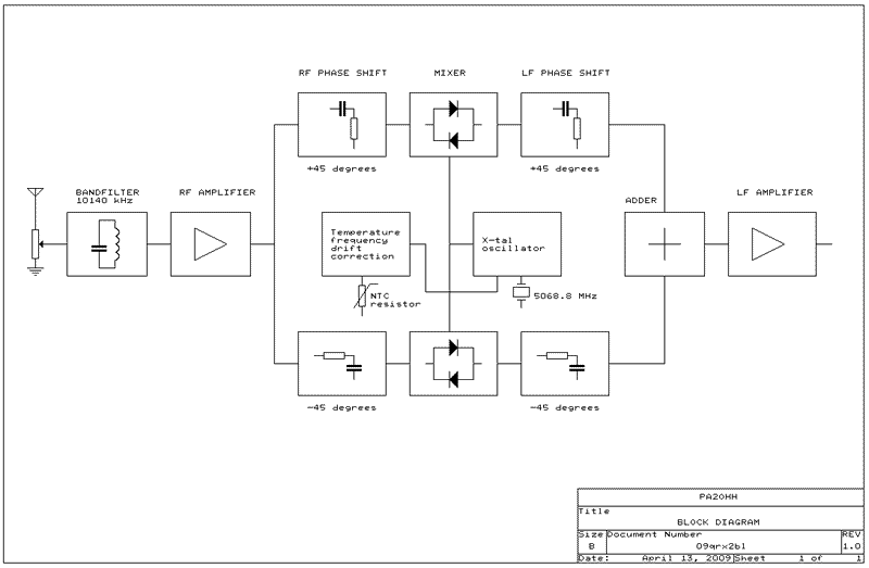
Block diagram. The phase networks do suppress 1 side band.
The Poljakov mixers do need a local oscillator signal of half the reception frequency.
Explanation of the schematic diagram
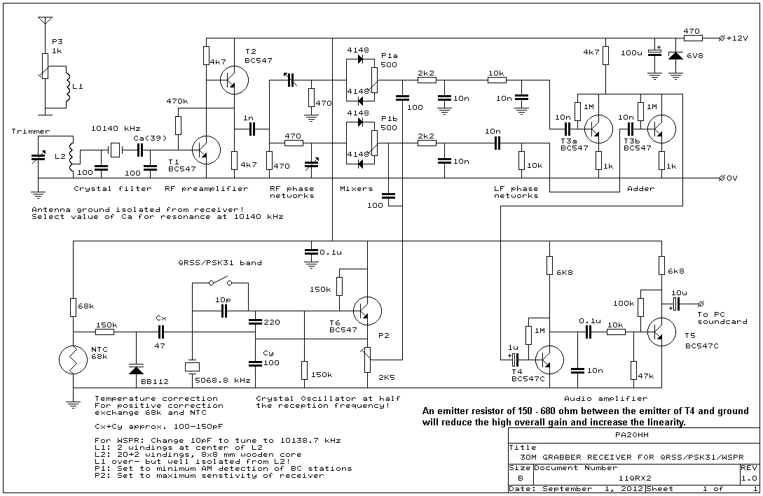
We will start with the RF amplifier and RF phase networks. T1 is an ordinary LF transistor. The tuned circuit is adjusted by ear for maximum sensitivity. L2 is 20 windings on a wooden core of 8x8 mm with a tap at 2 windings to the base of T1. The antenna winding L1 of 2 windings is wound at the cold side of L2. This antenna winding is completely isolated from the receiver, so that conducted radio interference cannot come into the antenna circuit. L1 is wire with a thick isolation, so that the distance between L1 and L2 is large and the capacitance small. Wind L1 at the cold side of L2.
The (adjustable) potentiometer P3 of 1k is the RF control. It is used to avoid overloading of the receiver in the evening by strong broadcast stations. You can use an adjustable potentiometer as it is not adjusted so often, only once or twice per day. But with the crystal filter, there is no overloading anymore and you can set it always to maximum!
T1 is followed by an extra transistor T2 that transforms the high output impedance of T1 to a lower impedance. That is necessary to feed the phase network.
There are two 45 degrees phase networks between the RF stage and the mixers. They are adjusted by the trimmers. For that purpose, you do need a signal at the unwanted side band. Adjust the trimmers by ear to maximum suppression of this signal. You have to repeat it a few times, as the settings of each network do influence each other.
Circuit diagram
Mixer and LF phase networks
The mixer is a so called RA3AAE or Poljakov mixer. It works with a local oscillator signal of half the reception frequency. And that is the frequency of a cheap, easily obtainable crystal of 5068.8 kHz. The oscillator level is quite important and can be adjusted by ear with P2.
With a good adjustment by ear of P1a and P1b, the sensitivity for strong AM signals can be reduced considerably.
After the mixer and the RF decoupling networks consisting of resistors of 2200 ohm and capacitors of 10 nF, you will find the LF phase networks. Each network is made of a capacitor of 10 nF and a resistor of 10 k ohm. The networks are designed for 1550 Hz, that is the center frequency of the 10140.0 - 10140.1 MHz band in my receiver. You have to modify them for other frequencies.
VXO
The crystal oscillator works approximately on 5068.8 kHz, just beside half the reception frequency. The exact value is not important, it is set during the calibration and corrected in the ARGO software program. By means of a switch and an extra serial capacitor, the frequency can be increased so that you also can receiver PSK31 stations working at higher frequencies..
Temperature stabilization
With a NTC resistor and a varicap, a temperature correction was designed and the drift reduced to less than 5 Hz between 10 C and 30 C. For an upwards frequency correction, the NTC has to be connected as in the diagram. For a downwards correction, exchange the NTC and 68k resistor. Of course you can also take a NTC resistor with another value. Exchange the 68k resistor then for a resistor with the same value as the NTC. Increasing Cx and reducing Cy increases the correction, reducing Cx and increasing Cy reduces the correction. Finding the correct value is a question of trying out while cooling down and warming up the receiver with various values of Cx and Cy.
The crystal filter
Between L2 and T1 is a simple crystal filter with 1 crystal of 10140 kHz, a series capacitor Ca and two capacitors of 100 pF to ground. The value of the capacitor Ca is chosen for resonance at 10140 kHz. For my crystal, 33 pF was too small (resonance frequency too high) and 47 pF too large (resonance peak too low). As I did not have a capacitor of 39 pF anymore, a capacitor of 18 pF and one of 22 pF were connected in parallel for a Ca value of 40 pF.
 |
 |
Side band suppression
only by the phase method |
Side band suppression
with extra crystal filter |
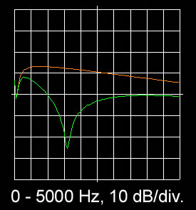
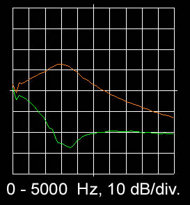
Frequency characteristic (orange line) and side band suppression (difference between orange and green line).
The reception frequency of 10140 kHz lies at the audio frequency of 1550 Hz in the graph.
The crystal filter is approximately 800 Hz wide. Wide enough to receive also WSPR signals between 10140.1 kHz and 10140.3 kHz. Strong signals outside the bandwidth of this very simple crystal filter are upto 30 dB attenuated! The AM detection of strong broadcast transmitters and also overloading of strong signals near the reception frequency are completely gone. The RF attenuator (the potentiometer P3 of 1k ohm at the input) does not have to be used anymore.
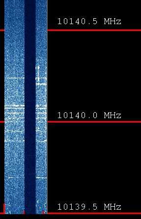
The spectrum. The noise peaks at 10140 kHz. When disconnecting the antenna, you can
see a dark strip in the spectrum. So the own noise of the receiver is really low.
Picture of the spectrum
The sensitivity of the receiver is excellent. You can see that on the picture here above of the spectrum. When the antenna is disconnected, you can see a dark strip in the spectrum, as the noise almost disappears. The noise of the receiver is almost negligible. In fact, the sensitivity is too good. Some RF attenuation is adviceable to increase the dynamic range. On the picture, you can also see that the filter peaks on 10140 kHz. At this frequency, the noise is maximal. With use of such a spectrum picture, you can easily determine the correct value of Ca.
Alignment of the receiver
The tuned antenna circuit at the input is aligned by ear at maximum sensitivity.
The value of the capacitor Ca is chosen for resonance at 10140 kHz.
The temperature correction is adjusted by warming up and cooling down the receiver with various values of Cx and Cy.
The oscillator level is adjusted by ear at maximum sensitivity. Adjust it a little higher, so that the sensitivity decreases a little. At that point, the suppression of strong AM broadcast signals is better.
The potentiometers P1a and P1b are adjusted with a strong AM signal in the 10 MHz broadcastband for a maximum suppression of AM detection. If possible, use a (simple) AM modulated signal generator.
The two 45 degrees phase networks are adjusted by ear with the trimmers. For that purpose, you do need a signal at the unwanted side band. Adjust the trimmers by ear to maximum suppression of this signal. You have to repeat it a few times, as the settings of each network do influence each other. If you want, you can optimize the side band suppression by changing the values of the resistors in the LF phase networks a little. Then repeat the alignment of the trimmers of the RF phase networks.
Software
You can find much information and software about QRSS on the internet. I did use ARGO of Alberto, I2PHD. But why should you only make your own hardware? Making software is perhaps even nicer! So nowadays I do use my own software LOPORA. So now and then, you can see the pictures at grabber.htm.
When you tune the receiver exactly to 10138.7 kHz, you can also receive WSPR with it. On the same PC, you can run at the same time ARGO software and WSPR decoding software and see and upload the results of both modes.
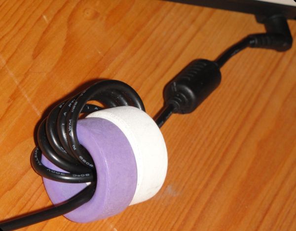
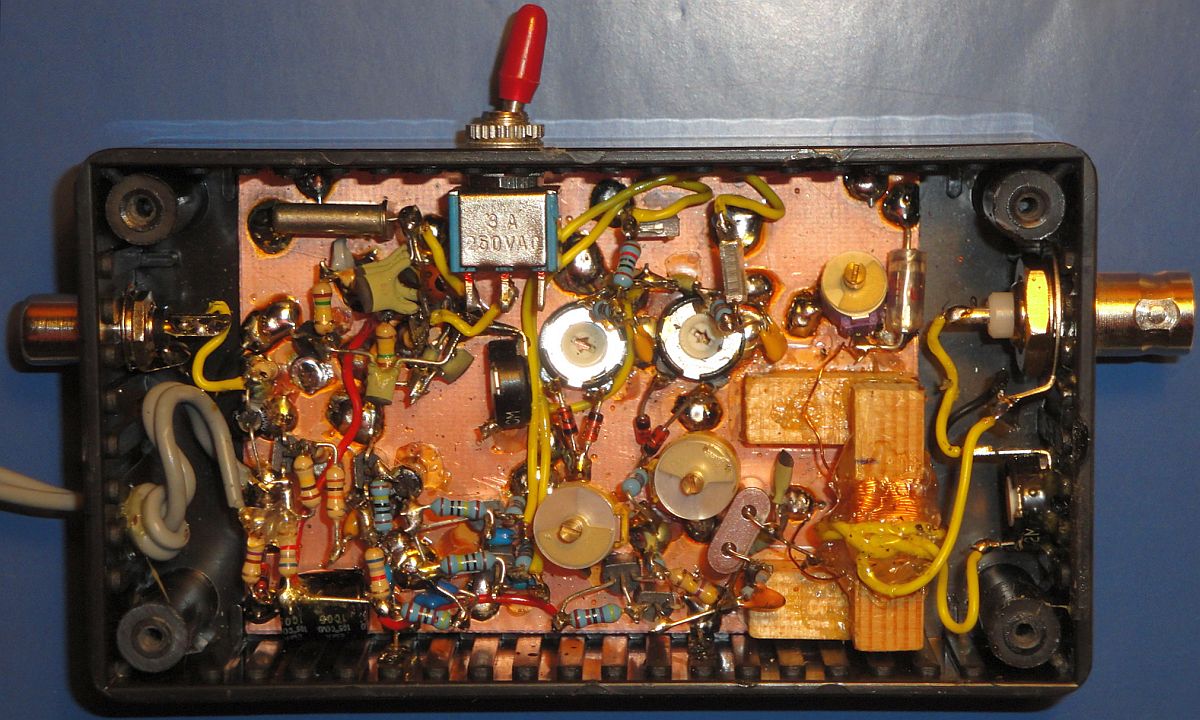
Ferrite ring cores in the supply cable and also the audio cable.
All other cables have been removed from the PC.
Interference suppression of the PC
In the supply cable and the audio cable, ferrite ring cores were fitted to suppress the radio interference of the PC. All other cables were removed. The LAN cable has been replaced by a wireless WLAN connection.
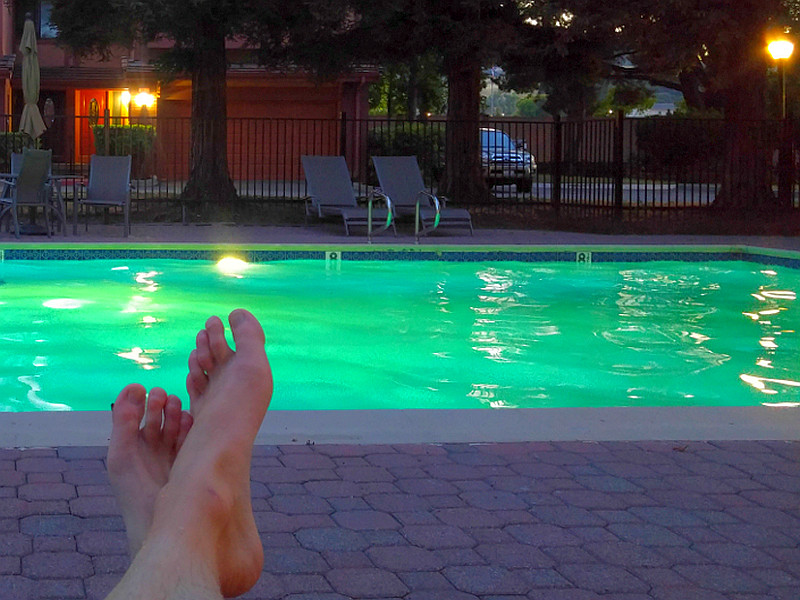
And now it is time to relax and wait for the results!
It is a nice receiver for holidays, the batteries last for more than one week!
Index PA2OHH