10 MILLIWATT BEACON TRANSMITTER FOR 30 METER
KEYED BY AN AUDIO PLAYER
(2011)
KLIK HIER VOOR DE NEDERLANDSE VERSIE
Experiments with very low power QRSS beacon transmitters
There is a group enthusiastic radio amateurs that is doing experiments with very low powers. That is possible by using a low CW speed (QRSS speed). Most of the activities can be found in a band of only 100 Hz, namely 10140.0 to 10140.1 kHz in the 30 meters amateur band. Signals are decoded with a special software program. My beacon transmitter could only be modulated with a square wave with a frequency shift of 4 to 5 Hz. But for the serious work, in morse code the call, QTH locator or transmit power had to be transmitted. But how can that keying with morse code be realized?
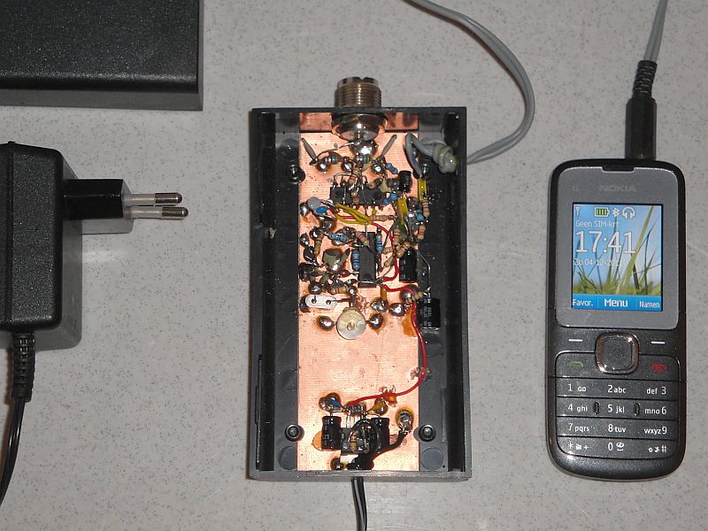
The beacon transmitter is keyed by a WAV file that is played by an
audio player (MP3/WAV player). Here I do use a mobile phone as an audio
player. But you can use all kinds of other audio MP3/WAV players of course.
Keying with an audio player
For keyng the beacon transmitter with morse code, I had already a solution with a light dependend resistor (LDR) in front of a PC monitor. On the screen was a black and white flashing square in the rythm of the morse code. But then, the PC had to be switched on all the time, 100 watt power to key a 10 milliwatt transmitter, what a waiste of energy! There had to be a better solution. For example an audio player! You can set the audio player so that it repeats an audio file all the time. For making the audio WAV file, a computer program in Python was written. My call in morse code with a dot length of 3 seconds and also an audio file with a dot length of 6 seconds. When you want to change the dot length, you do not have to re-program a micro controller, but you simply select another audio file on the audio player! And the beacon transmitter was modified so that it could be keyed by the incoming audio signal. A detector makes zeroes and ones of the morse code tones. And... my mobile phone can also pay WAV files! I do not use that telephone to make telephone calls, I do not have friends. When you do use a telephone as audio player, take out the SIM card, otherwise incoming telephone calls can disturb the modulation. But you can also use all kinds of other WAV/MP3 players of course.

Circuit diagram
big diagram
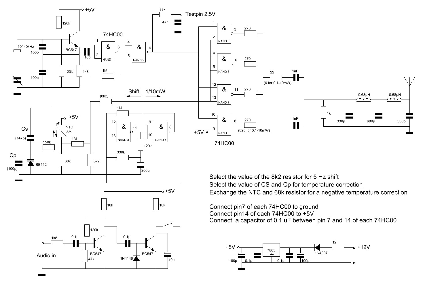
Description of the circuit diagram of the transmitter
A crystal oscillator with a BC547 transistor is buffered by NAND1 and NAND2 and amplified by NAND5 to 8. The circuit with NAND3 and NAND4 is a square wave oscillator. When the switch is opened, the transmitter is frequency modulated by this square wave. But also in amplitude. During the positive half of the square wave, NAND5 to 8 are all switched on and the transmit power is 10 mW. During the negative half of the square wave, only NAND8 is active and the transmit power is only 1 mW (or 0.1 mW, depending on the used resistor values). When the switch is closed the transmitter is keyed by the audio signal of the audio player. The left BC547 does amplify this signal, the right BC547 with diode 1N4148 is the detector that makes zeroes and ones out of it. Set the volume control quite high. The capacitor of 10 uF does suppress the audio and other interferences.
During the transmission of a dot or dash, the transmit power is 10 milliwatt. During spaces, the transmit power is 1 milliwatt (or 0.1 mW, depending on the used resistor values) and the transmit frequency is lowered with 4 to 5 Hz. But for the current experiments, the beacon does transmit both shifts with 10 mW. The NAND's are all connected to +5V instead of to the output of NAND3.

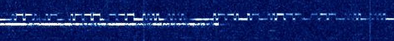
The transmit signal of the beacon transmitter, keyed by an audio
player (MP3/WAV player). Here, the power of both shifts is 10 milliwatt,
but you can also transmit with a lower power during the lower shift.
Temperature stabilization
The frequency has to be very stable. It is quite difficult to adjust the beacon transmitter on a frequency of 10140.0 tot 10140.1 kHz and to avoid drift due to temperature changes. A temperature correction circuit was made with a NTC resistor and a varicap. The drift could be reduced considerably. For a positive frequency drift correction, you have to connect the NTC in accordance with the diagram. For a negative correction, the NTC resistor and 68k resistor have to be exchanged. Of course you can also take a NTC resistor with a different value. Exchange the 68k resistor then for one with the same value as the NTC. Increasing of Cs and reducing Cp increases the correction, reduction of Cs and and increasing of Cp does reduce the correction. Finding the correct value is a question of trying out while cooling down and warming up the transmitter with various values of Cs and Cp. Between 5 and 35 �C, the temperature drift is only 4 Hz.
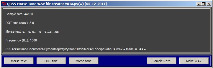
The Python program to make the WAV audio file.
How to make the WAV file
For making the WAV file with the morse code, many programs can be found on the internet. I did use an in Python written program.
See for a description of this program: 11qrssmo.htm
Results, both shifts 10 mW (click on the pictures to see the originals)
It works! The beacon transmitter is transmitting during many week now with the audio player without interruptions or any problems. Boths shifts are transmitted with 10 mW.
Reports
I received via e-mail beacon reports from YO7CKQ (Romania). Many thanks!


The 10 mW beacon signal received by YO7CKQ - (KN15pa).
And also via e-mail a report from Johan, PA0TAB, who lives approximately 20 km from my QTH.

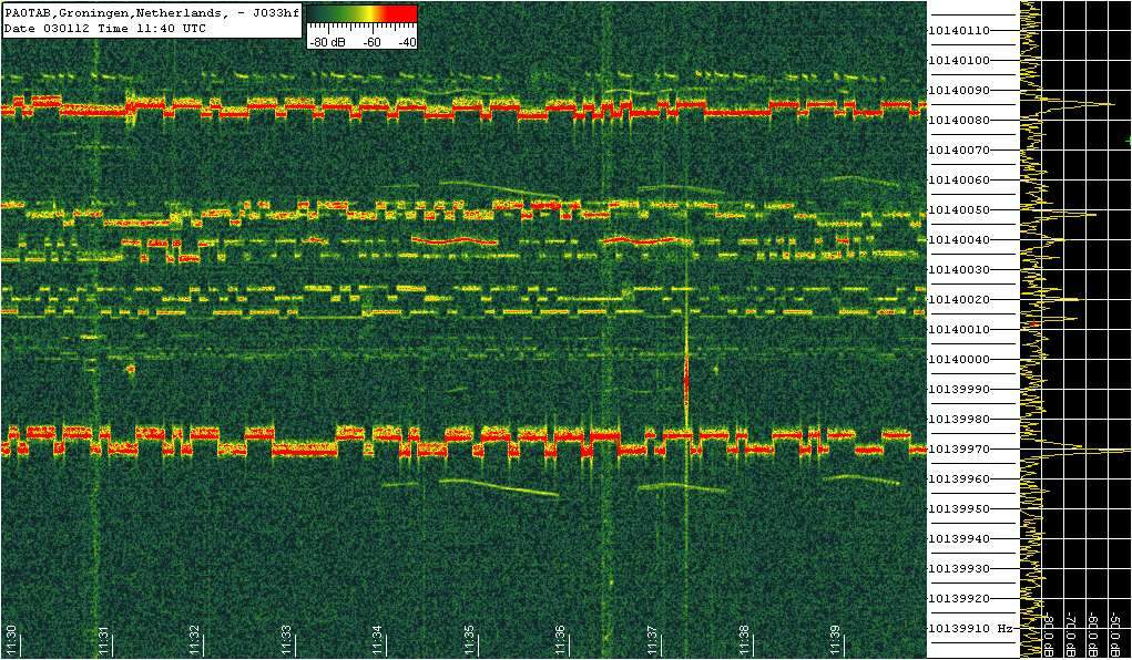
The 10 mW beacon signal received by Johan, PA0TAB (20 km from my QTH).
Grabber of Johan, PA0TAB: http://pa0tab.nl/grabber.html
Grabbers
But there are other possibilities to collect reception reports. There are amateurs who have their receivers coupled to internet. The reception results are continuously refreshed. You can see these results on internet (Search via Google for "QRSS grabbers"). The results here below were obtained via these QRSS grabbers.

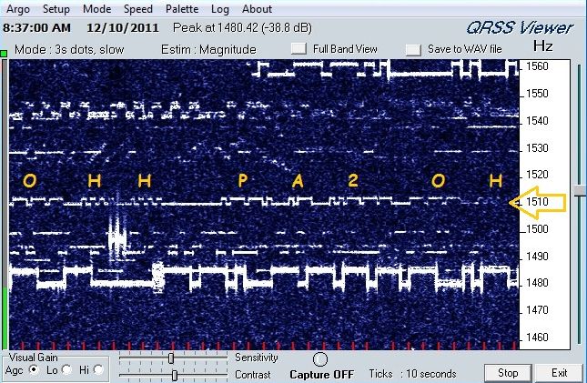
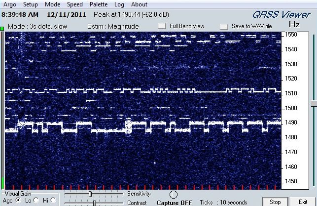
The 10 mW beacon signal received via the grabber of G4CDY - TERRY (IO91wh).

The 10 mW beacon signal received via the grabber of IK1WVQ - MAURO (JN44cb).

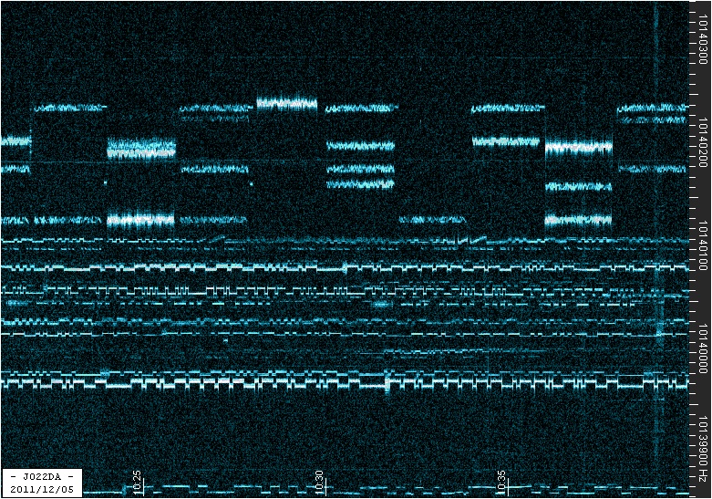
The 10 mW beacon signal received via the grabber of PA1GSJ/DL1GSJ - JOACHIM (JO22da).

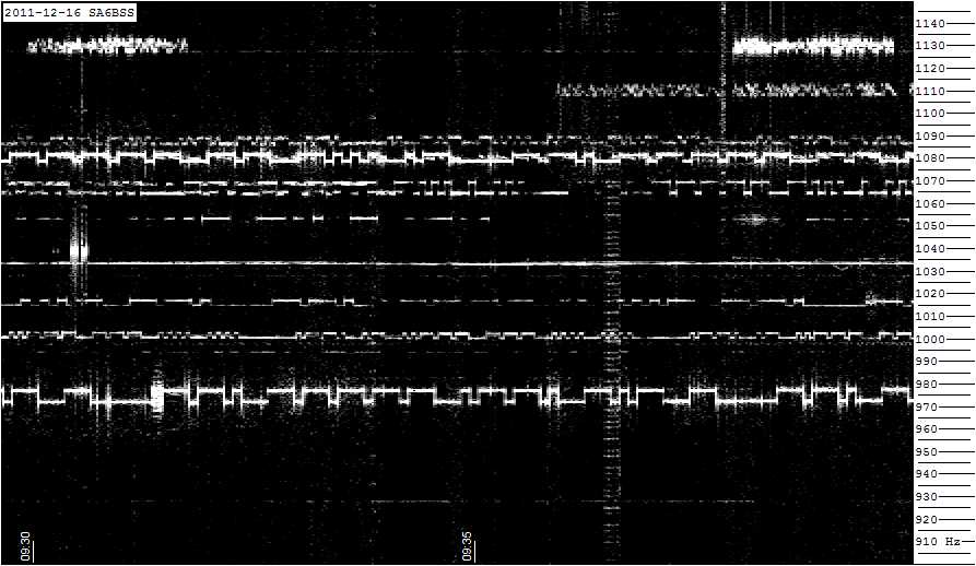
The 10 mW beacon signal received via the grabber of SA6BSS (JO68sc).
Holidays
And you can go travelling to a location! Here some reception reports of the beacon during holidays in Spain!


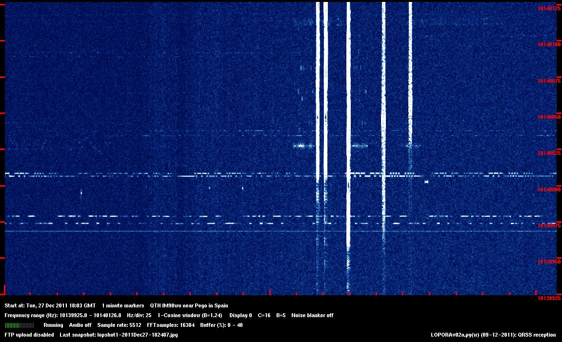
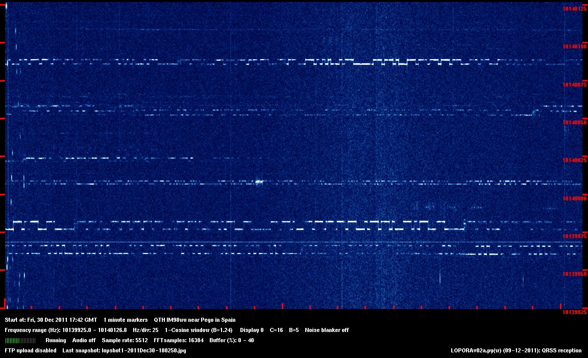
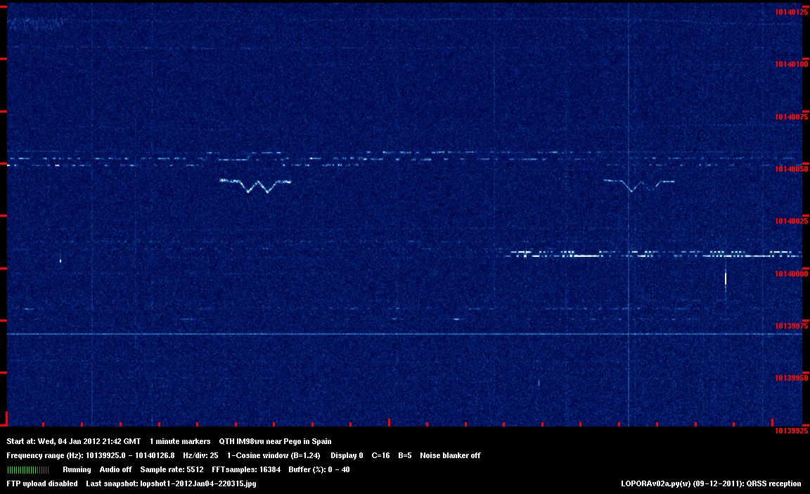
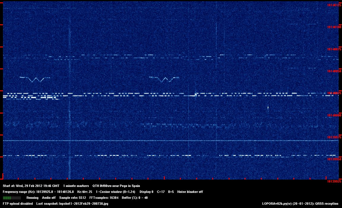
The 10 mW beacon signal received during holidays in Spain (IM98wu).

The 10 mW beacon signal received during holidays in Spain (IM98wu).
Here 12 pictures mean stacked with the program RotAndStack.
(http://www.gdargaud.net/Hack/RotAndStack.html)
Results, low shift 1mW, high shift 10 mW (click on the pictures to see the originals)
And here two results with the low shift of 1 mW and the high shift of 10 mW.


The 1 mW low shift - 10 mW high shift beacon signal received by YO7CKQ - (KN15pa).

The 1 mW low shift - 10 mW high shift beacon signal received by the grabber of IK1WVQ - MAURO (JN44cb).
And... You can take the QRSS beacon receiver with you during holidays to try to receive the beacons signal with 1 mW low shift - 10 mW high shift!

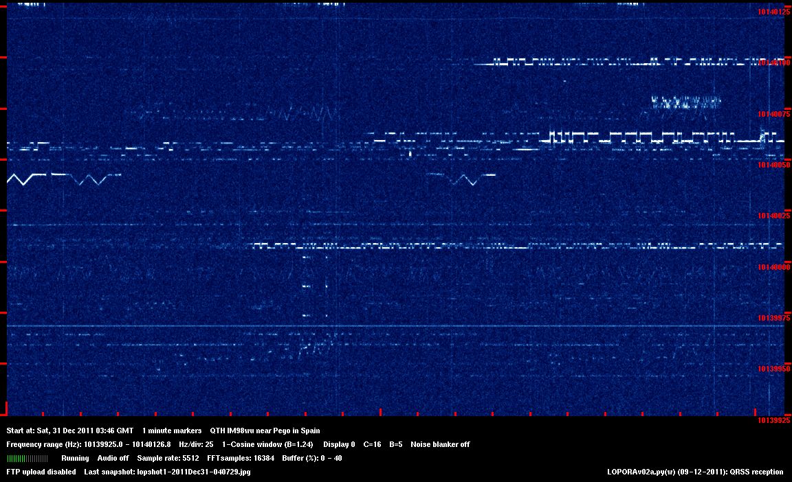
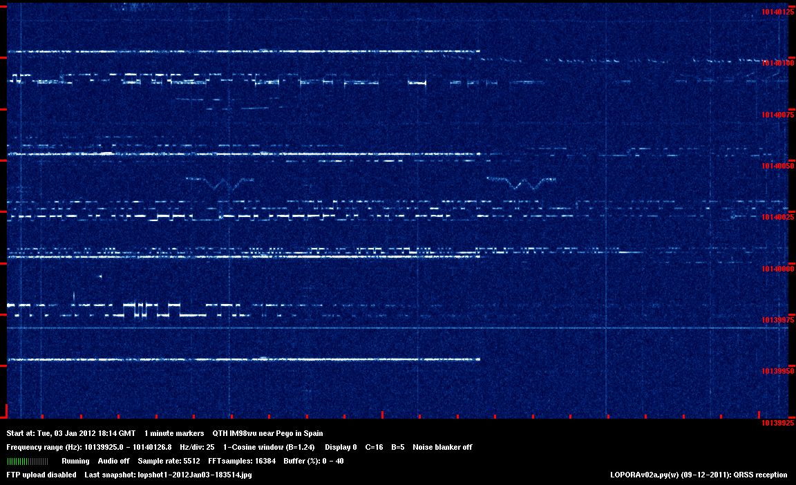
The 1 mW low shift - 10 mW high shift beacon signal received during holidays in Spain (IM98wu).

The 1 mW low shift - 10 mW high shift beacon signal received during holidays in Spain (IM98wu).

The 1 mW low shift - 10 mW high shift beacon signal received during holidays in Spain (IM98wu).
Here 9 pictures sort stacked with the program RotAndStack.
(http://www.gdargaud.net/Hack/RotAndStack.html)
BACK TO INDEX PA2OHH


