A SIMPLE FREQUENCY METER
(2010-2018)
KLIK HIER VOOR DE NEDERLANDSE VERSIE
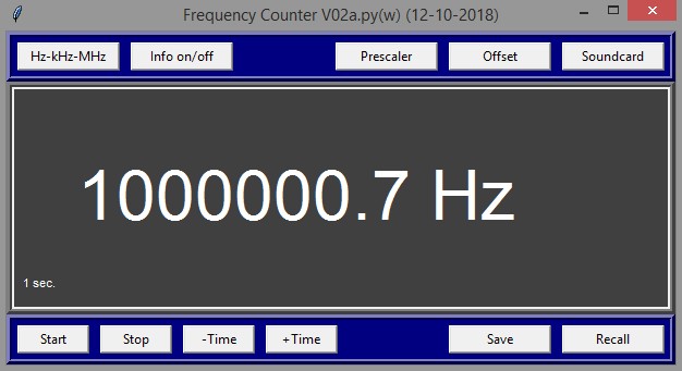
The frequency meter. The program is written in the programming language Python.
Therefore, it is simple to adapt it to your own requirements.
A simple frequency meter for the PC with a soundcard
No primitive frequency counters with leds anymore! Throw them away! We replace these simple frequency counters by a real display on the PC. That looks much nicer, is not so primitive and the hardware is simpler too, only 1 IC! And the frequency is much simpler and nicer readable and more accurate!
The idea is very simple and applied more often. We divide the RF signal with a prescaler to audio frequencies. This audio signal is connected to the soundcard of the PC and we measure the audio frequency. Then this frequency is multiplied with the prescaler value and... we do have the RF frequency!
When you press "Stop", then the current settings are stored in the file "recent.jpg" and loaded when you run the program the next time.
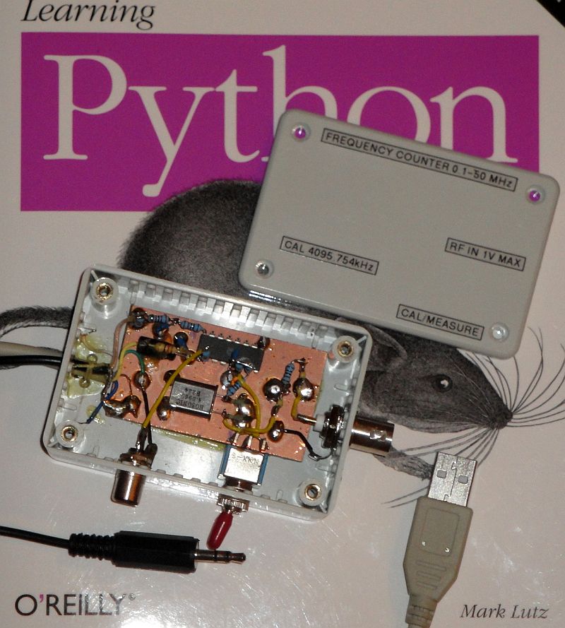
The hardware, a very simple box.
Measuring principle and accuracy
A frequency counter counts during a certain time the number of periods. This frequency counter works differently. Of a certain number of periods, the exact time is measured.
The resolution of this time measurement depends on the sample rate of the soundcard. The resolution of the time measurement is plus or minus 1 sample. But by adding one extra resistor and one extra capacitor, the accuracy can be improved by a factor 20x! And with fast measuring times of 0.2 seconds, that you want to use for tuning a receiver, we still do have a good accuracy.

When the slope is reduced by means of an RC network, we do also have
amplitude information and we can calculate where between both
samples the zero crossing is.
Trick to improve the accuracy
With a square wave signal from the prescaler, we do not know where exactly between the two audio samples of the soundcard the zero crossing is. The first sample is always +5 volt and the next sample 0 volt. So the accuracy of the time measurement is always plus or minus 1 sample. But when we could calculate where exactly the zero crossing is between the two samples, we can also measure with fractions of samples and then the accuracy of the time measurement is much better! And that is possible! When the slope is reduced by means of an RC network, we also have amplitude information and then we can determine on which place between both samples the zero crossing is! Is U2 smaller than U1, then the zero crossing is closer to S3 than to S2. And with the ration U1:U2, we can calculate exactly where the zero crossing is!
Prescaler upto at least 30 MHz with built in frequency reference.
With an extra prescaler, you can expand the range upto a few GHz.
Hardware
At the input, you will find a limiter to prevent damage. It consists of a resistor R1 of 1k ohm and two diodes connected anti parallel. With S1 in the lower position, the RF signal goes to the input of the 74HC4060. This IC divides the RF signal by 4096 to an audio frequency. At the output of the 74HC4060, you can find the RC network of 10k ohm and 10nF to reduce the slope. And the resistor network of 22k and 1k does attenuate the audio level so that the soundcard is not overdriven.
The two resistors of 1M are for the correct DC setting of the input. The capacitor of 10nF does filter the AC component. Otherwise there is feedback that reduces the gain at low frequencies.
With S1 in the upper position, the 74HC4060 does work as a crystal oscillator, and then you have a reference frequency for the calibration of the soundcard. It is also possible to use a different crystal of course. You do not have to adjust the frequency. My copy has a frequency of 4095.754 kHz and I enter that frequency during the calibration.
The circuit is supplied via the USB port. Go to the shop for a cheap USB cable, cut of the right plug, find the right wires and you do have a 5 volt supply. As the supply voltage is 5 volt, you can also use the better available 74HCT4060 instead of the 74HC4060. There is an extra output in the circuit for a 4 kHz / 5 volt calibration signal for a simple oscilloscope working with the soundcard.
Frequency
(MHz) | Sensitivity
with R1=120
(mV RMS) | Sensitivity
with R1=1k
(mV RMS) |
0.03
0.1
1
10
20
30
50
80
100
120
|
15
10
3
10
25
30
100
150
200
500
|
15
10
5
20
50
100
300
1000
-
-
|
Sensitivity of the simple prescaler.
Accuracy
Tests were performed with the internal soundmodule of a laptop and with a simple, exteran USB audio device. The calibration signal of 1 MHz comes from aGPS locked module.
The internal sound module gave a deviation of +20Hz. The USB audio device had a deviation of -75Hz.
After calibration, there was a variation of 1 to 2 Hz in the measured values. This is tested with a measuring time of 1 second.
Setting of the sound module
Set the sample rate to the default value of your operating system. Usually that is 44100 Samples/sec.
You can connect the prescaler to the line input or to the microphone input of the sound card. When you use the microphone input, you must switch off the extra 20 dB amplification. Adjust the input level so that this level is well below the maximum of 100%, for example 5% -20%. With the mouse you can adjust the volume control of the sound module. How this has to be done, depends depends on the used sound module, your operating system and its version.
Calibration
There are two possibilities for the calibration:
Possibility 1: Select "Prescaler" and enter manually the prescaler value.
The prescaler value has to be chosen so that the exact value of the frequency is displayed. So not 4096, but for example 4096.0235.
Possibility 2: Connect the frequency meter to a reference frequency and do a measurement with a long measurement time of 5 seconds.
Click "Stop" to stop the measurement. Select "Prescaler" but press "Cancel" instead of to enter a prescaler value.
Answer the question "Calibrate with measured frequency" with "yes" and enter the reference frequency in Hz. The exact prescaler value is calculated automatically. You can store it together with the other settings like offset frequency. For the calibration, you can use the in the prescaler built-in crystal oscillator of course.
Other applications
Many amateurs circuits do have a frequency stabilizer (for example a Huff & Puff), with which the VFO signal is already divided by a prescaler (for example a 74HC4060) to audio frequencies. The only things you have to add is the simple RC network consisting of 3 resistors and 1 capacitor and a cable with plug. The IF frequency can be programmed as a frequency offset and we do have a very nice frequency display. Very often, the PC is already connected to the receiver to decode digital modes. A switch for "audio out" or "prescaler out" is then very handy.
SOFTWARE
Before you use this program, you have to install Python. That is very simple. But read first something about Python by clicking the following link:
WHAT IS PYTHON AND HOW DO YOU INSTALL PYTHON
As the source code of Python is written in ASCII, it is very simple to modify the program to you own requirements. Think for example about the size of the screen, the colors etc.
Required Python version:
Required external modules (site-packages for the correct Python version!):
Download here the Python frequency counter program by clicking the link here below:
Index PA2OHH