BINARY DECIMAL LED DISPLAY VERSIONS
OF THE SIMPLE FREQUENCY COUNTER
(2004)

Very relaxing with bare feet and a very unusual, very creative transceiver
with a binary decimal display. What a wonderful hobby radio is!
Why a new version of the LED display?
There are other display methods than the original 8 led frequency counter has. They are perhaps easier to read and may have a format that fits better to the front of your QRP equipment. Here some examples of binary decimal displays are given.
7 LED BINARY DECIMAL DISPLAY
(2004)
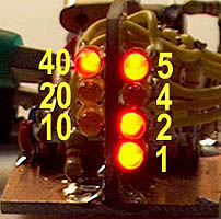
7 LED binary decimal display.
Mostly the the counter is made without the MHz position, only the kHz position is used to read the VFO frequency within a 100 kHz segment. This counter uses only 7 leds for reading the frequency in a 100 or 50 kHz segment. The counter starts counting at zero at each multiple of 100 or 50 kHz. Gating is done after the first /2 divider.
In this version, also the preamplifier is deleted and 74HCT390 chips are used instead of a 74HC390 for maximum sensitivity. The first /2 divider is adjusted for maximum sensitivity with a DC bias voltage. Gating is done after this first /2 divider. Of course it is also possible to use 74HC chips plus the RF preamplifier. In this case, the RF preamplifier is supplied by the 5V supply and not by the gating pulse. The advantage is that the RF amplifier is not switched on/off by the gating signal which might influence your VFO frequency due to the varying load.
Reading your frequency with an accuracy of 500 Hz is possible
as the least significant led (2 or 1 kHz) works like an analog scale.
|
A display of 1, 2, 4, 8 kHz is also possible by placing
the second /2 divider between the first /2 and /5 divider
of the 74HC(T)390. Or: /2 /2 /5 /5 instead of /2 /5 / 2 /5.
|
The least significant led (2 or 1 kHz) works like an analog scale. It slowly varies in brightness when the frequency is changed. Therefore, the frequency reading is much better than the value of that led.
Circuit diagram of the 7 led display counter
big diagram
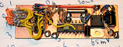
The experimental version of the 7 led frequency counter
including an extra 5V stabilizer circuit with a 7805.
This photograph shows good how very simple the counter is!
Calibration of the frequency counter
Select the Rcal value for a correct display of a reference frequency. See the 2x4 LED frequency counter above
for an explanation.
Notes
Use 3mm low current leds.
You should build the counter in a screened box to avoid RF interference in your receiver!!
Performance.
At 30 MHz, the frequency error was +100 Hz. At 10 MHz, the error was -300 Hz.
Supply current is 3 to 7 mA, depending on the number of illuminated leds and the input signal.
Frequency
(MHz) |
Sensitivity
(mV rms) |
0.1
1
10
20
30
50
60
63
|
20
20
30
50
100
300
500
1000
|
Note:
The sensitivity is quite good but for a reliable operation over a wide
temperature range, the input signal should be at least 100 to 200 mV.
THE BINARY DECIMAL 2x4 LED DISPLAY
(2004)
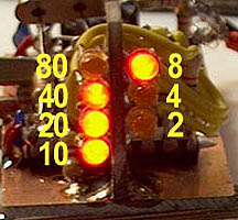
The binary decimal 2x4 LED display.
Instead of the original 8 led binary display, we can also make a 2x4 led binary-decimal display.
Here a more complex version of the simple frequency counter with 4 chips, it has a kHz and a MHz mode:
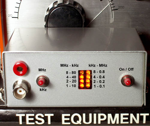
2x4 LED binary decimal display. The left row is the x10 kHz / x10 MHz display,
the right one the x1 kHz / x1 MHz display.
Circuit diagram
big diagram
Working principle
The 74HC4040 in the original 8 led counter is replaced by a 74HC390. This chip has two /10 dividers so that we will have that new display with 2x4 leds instead of the 1x8 led display. A 74HC00 (do not use a HCT) is added, one NAND is used as RF preamplifier to increase the sensitivity and as buffer between the VFO and counter, another as an RF gate switch to start and stop the counter. The unused inputs of the two remaining NAND's are grounded. Using a 74HC00 instead of the transistor amplifier eliminates the problems with the settling time of the RF transistor amplifier of the original two chip frequency counter. The chip is even cheaper than the transistor but needs more supply current!
It works as follows: We reset the 74HC390, then count, then stop counting and display the frequency and then reset again etc.
The 74HC4060 oscillator with the 4096 kHz X-tal generates a frequency of 500Hz. Only the +5V half period is used for counting. During the +0V half period, the leds are displaying the frequency, during the +5V half period, they are off and the 74HC390 is counting the frequency. At the beginning of the counting period, the 74HC390 is reset by the short reset pulse from the 100 pF/Rcal differential network.
The gating is very critical as a 1 to 0 transition from the 74HC00 gate will cause an extra count. This does not occur when the gate switches off, then the output goes from 0 to 1 (or 1 to 1). But when the gate switches on while the input is 1, the output of the gate is changes from 1 to 0. However, during this moment the reset pulse is active, preventing that extra count.
Explanation of how it works: counting if gate signal=1, display frequency if gate signal=0.
The short reset pulse is made by the 100pF/Rcal differential RC network.
Calibration of the frequency counter
Normally, the calibration is done by adjusting the crystal frequency with a trimmer. But not here! Due to the 100pF capacitors, the oscillator frequency is lower than the crystal frequency. The resulting gating pulse is a little too long. But the frequency measurement time is the length of the gating pulse minus the reset pulse. Calibration of the frequency counter is done by changing the length of the reset pulse (depending on Rcal value). Select the Rcal value for a correct display of a reference frequency.
Notes
Use 3mm low current leds.
You should build the counter in a screened box to avoid RF interference in your receiver!!

Only barefoot simple tools were used for the construction of
the barefoot simple frequency counter with binary decimal display!
Performance.
At 30 MHz, the frequency error was +300 Hz. At 10 MHz, the error was 100 Hz. In the MHz position, the accuracy is the same as in the kHz position because the same gate pulse and reset pulse are used.
Supply current including a 78L05 stabilizer is 10 mA with an input signal and 50 percent of the leds on, 25 mA without input signal as the supply current of the 74HC00 is much higher without an input signal.
Frequency
(MHz) |
Sensitivity
(mV rms) |
0.1
1
5
10
20
30
50
60
80
85
|
40
10
15
15
25
50
150
200
500
1000
|
Index PA2OHH