IMPROVED CRYSTAL RECEIVER
FOR THE MEDIUM WAVE (AND SHORTWAVE)
(2003)

The improved crystal receiver.
WHAT YOU CAN HEAR WITH SUCH A SIMPLE CRYSTAL RECEIVER
All stations were heard without using any amplifier!
Just the passive diode detector and crystal telephone are used with a 20 meter long wire antenna at a height of 4 to 5 m!
Total listening time during 2 days was only 3 to 4 hours!
What is the trick
That is an extra antenna tuner to improve the selectivity and sensitivity!
And there is the fading! Stations vary considerably in strength due to fading. Sometimes they are quite strong for a few minutes, then they disappear and other stations can suddenly be heard. So be patient, keep listening, tune the antenna tuner to maximum sensitivity or selectivity and let the fading do its work.
Diagram of the improved crystal receiver with antenna tuner.
Description
This passive receiver is a combination of an antenna tuner with an original crystal receiver. The antenna tuner improves the sensitivity and selectivity considerably as it tunes the antenna to resonance for the reception frequency.It also suppresses breakthrough of shortwave stations.
The tuner and receiver coils are wound on 8mm ferrite rods (0.3 mm copper wire). The rods are provided with a knob and movable, so the value of L1 and L2 can be varied by moving the rods in and out the coils. For shortwave reception they are removed completely.
With L1B (switch S4), the inductance can be increased for the lower end of the medium wave band, the capacitors C1 and C2 can be increased with an extra 160 pF with S3 and S2. With S1, the diode can be connected to a tap instead of the top of L2. Below 1 MHz, the top position was the best one, the tap did only decrease the sensitivity without affecting the selectivity. Above 1 MHz, the tap gave the best selectivity without losing sensitivity.
S2 is added to cover the frequency range below 750 kHz as the value of the variable capacitor was too low or the number of windings of L2 should have been a little more... Connect the tuner part with a jumper wire to that tap of L2 that givest the best selectivity or best sensitivity.
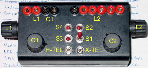
Top view
How to use the antenna tuner
The antenna tuner tunes the antenna to resonance. Impedance matching is done by choosing the optimum tap of L2.
With jumpers, the tuner can be used in 3 ways:
- L1 and C1 in series. This is the preferred method with maximum selectivity. Tuning is done by C1 and L1A. Selectivity is maximal if L1B is switched in series with L1A.
- L1 only, for the lower frequency range if it is not possible to tune the antenna with method 2. Tuning is done by moving the ferrite rod in and out L1A.
- L1 and C1 in parallel, for the lower frequencies and short antennas (see first picture). Tuning is done by C1. However, use of this method should be avoided, take one of the next two if possible.
However, it depends on the antenna etc. which combination is the best. And of course you need a (good) ground system! I use the central heating for that.
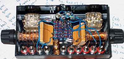
Inside view
The diode
I did some experiments with schottky and germanium diodes. The germanium diodes were always better, but please look at various articles on the internet about diodes for crystal receivers. I took the AA119 that was available here in the "museum" box. A very old OA81 showed similar performance. The resistor of 100 k after the diode gave good results and is not critical.
Medium wave and Shortwave reception
It is possible to receive the medium wave and shortwave. For shortwave reception, the ferrite rods are removed. It is also possible to connect the antenna directly to the lowest tap of L2 without using the antenna tuner. Shortwave signals are very strong! For the higher shortwave frequency bands, shorten the taps 32 and 70 with a jumper (ferrite rod removed of course).
Headphones instead of the crystal telephone
Quite good results were obtained with normal hifi stereo headphones instead of the crystal telephone. A 230 to 6 or 12 volt transformer was used for impedance matching. The primary 230 V was connected to the output of the crystal receiver, one earpiece (or two earpieces in series) are connected to the secundary 6 or 12 V. Sound quality was better, sensitivity not much less than with the crystal telephone. However, it will depend on the type of transformer and headphones you are using. The 100 k resistor can be removed.
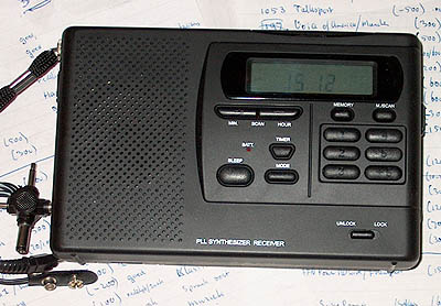
Radio with digital display for identification of the stations
Tools for Medium Wave DX ing with the crystal receiver
I use a (non connected) headphone over the crystal telephone to eliminate background sound. It also holds the crystal telephone on its place.
For identification of the stations, a simple digital portable receiver is very useful to determine the exact frequency. But be careful, some stations are on more than one frequency!
On the internet you can find the European Medium Wave Guide (search for European Medium Wave Guide). Very useful of course to identify the stations when you have found the exact frequency with the digital receiver.
Improved, but it can still much better!
This is only an improved crystal receiver, not a top performance design. But as you can see from the table of received stations, the results are not bad, 45 stations received during listening for only two evenings (3-4 hours totally). On the internet you will find a lot of information about how to make a real top performance crystal receiver with balanced armature headphones (often called sound powered headphones), very high Q coils etc.
BTTF contest!
In December 2003, a contest was organized here in the Netherlands. The name was Back To The Future (BTTF). The challenge was to log as many medium wave stations as possible with a passive receiver.
Click HERE if you want to download the zipped bttf2003.doc log of the stations I heard with this crystal receiver during that contest.
Index PA2OHH