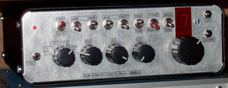
The simple shortwave receiver for CW and SSB.
SHORTWAVE RECEIVER
10 kHz - 30 MHz
(2002)
KLIK HIER VOOR DE NEDERLANDSE VERSIE
The simple shortwave receiver for CW and SSB.
No AM reception
The receiver does not have AM reception. But if you want, you can receive AM in SSB mode. The advantage is that there
is no distortion due to selective fading.
Speech sounds acceptable, just like SSB, music sounds like an old 78 rpm gramophone...
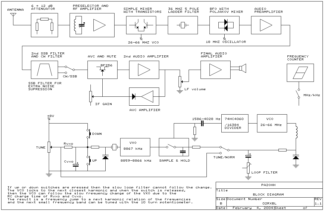
Block diagram
Lower Side Band and the Ladder Filter
What a shame that those amateurs still use LSB below 10 MHz. And they can't keep it up... Unfortunately, the sideband suppression of a ladder filter is much worse when the BFO frequency is at the bottom of the filter, as is necessary here for LSB reception. But we also have a solution for that. We start the VFO at 26 MHz instead of 36 MHz. For LSB reception we then tune this VFO below 36 MHz instead of above and we also have good sideband suppression for LSB. So there is no USB/LSB switch!
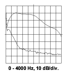 A ladder filter with 48 MHz crystals in USB mode, the BFO frequency is at the top of the filter. The upper trace is the filter curve, the lower the suppressed sideband. |
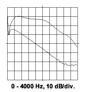 The same ladder filter but now with the BFO frequency at the bottom of the filter as required for LSB reception. The sideband suppression is now much worse! |
A closer look at the details
Do not attempt to copy this receiver exactly. Of course that is possible, but do not hesitate to realize your own ideas and improvements and use parts that you still have or that better suit your working method.
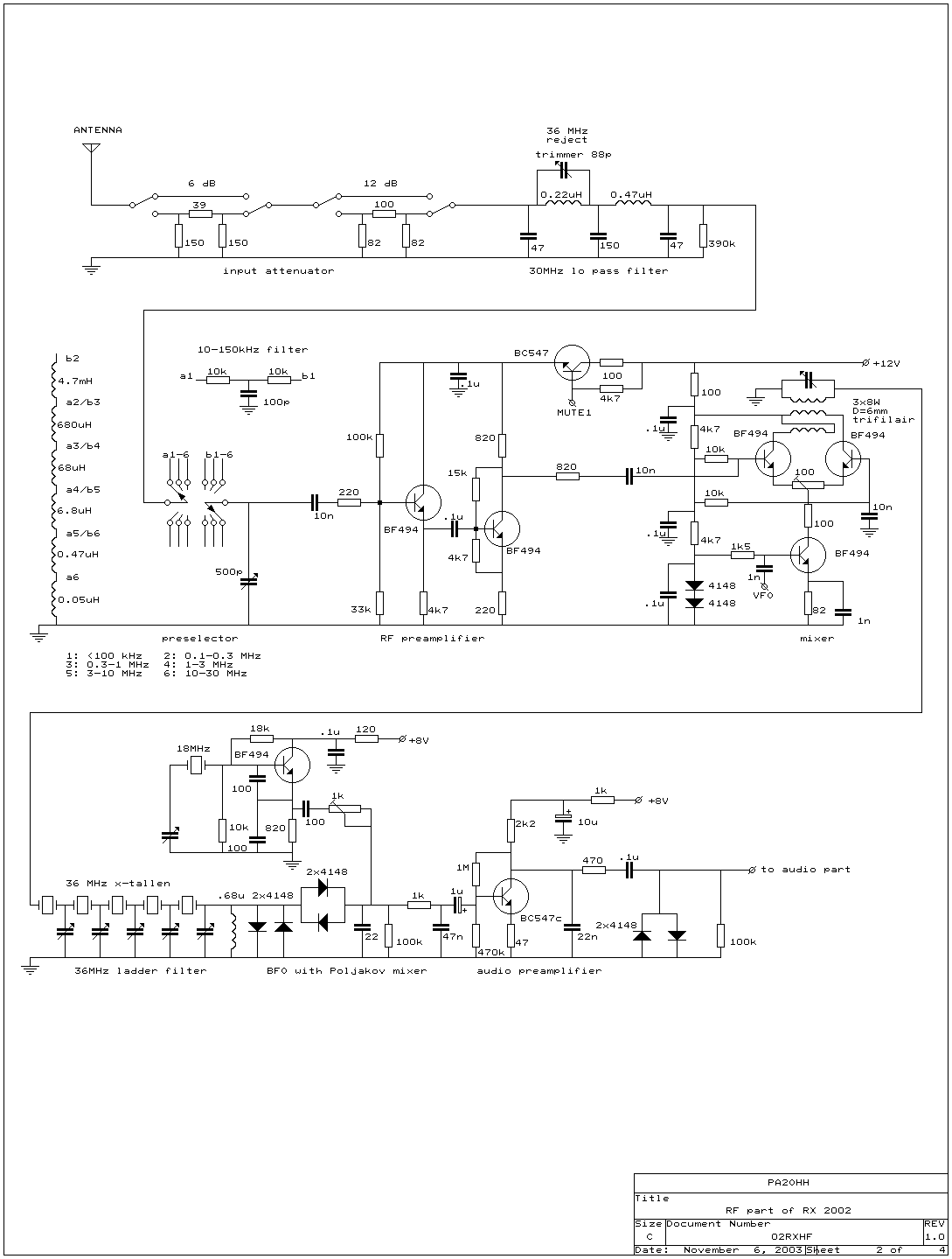
HF circuit
Mixer with transistors
My first receiver had an SL6440 IC as a mixer. Incredibly good! But that was not the intention here. I was curious about the behavior of an ordinary old-fashioned mixer with transistors, I also wanted to use standard parts and so this mixer was chosen. It certainly works well, but if there is anything to improve, I would start here. Replace it with an NE612 or better, an SL6440. You then have a double balanced mixer instead of a single balanced mixer. The intermodulation behavior, the suppression of 36 MHz signals via the antenna input and also the buffering of the VCO are better.
The 820 ohm resistor between HF amplifier and mixer may be omitted. But without this resistor, a signal of 10 dBm on the input of the receiver caused so much disturbance towards the VCO that it changed frequency.... These signal strengths only occur when you switch on your own transmitter on a second antenna.
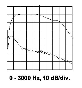 The 36 MHz ladder filter adjusted for maximum sideband suppression, 40 dB at 600 Hz. The upper trace is the filter curve, the lower the suppressed sideband. |
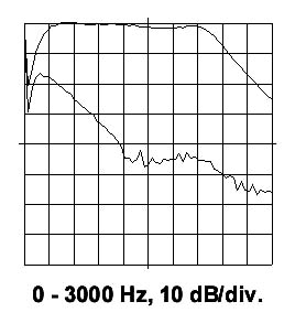 The 36 MHz ladder filter adjusted for optimal flatness. The sideband suppression is now less but still 25 dB at 600 Hz. |
Ladder filter
The ladder filter is made up of 5 crystals of 36 MHz that are connected to each other via 40 pF trimmers. You probably need to have a bit of luck with the accuracy and quality, just like with everything else in life. With the trimmers you can adjust the bandpass for maximum sideband suppression or optimal flatness of the filter. The easiest way to adjust is with a noise source and an audio spectrum analyzer program via the PC sound card. The ladder filter is followed by two anti-parallel connected diodes as a limiter for strong interference peaks.
BFO and low frequency preamplifier
The BFO is very simple: two anti-parallel connected diodes. This mixer is also known as the Polyakov mixer or the RA3AAE mixer. It was chosen because the injection frequency is half of the 36 MHz signal or 18 MHz. A cheap crystal can now be used for the BFO. An oscillator with a fundamental crystal is much easier to realize and can be set to the correct frequency much easier than an oscillator with an overtone crystal. The proper functioning of such a mixer depends on the (sinusoidal!) oscillator signal. Adjust the 1k resistor to maximum audio level when receiving a CW signal.
After the BFO, an LF amplifier follows to amplify the signal a bit before the audio filters start adding some noise. By changing the value of the 47 ohm emitter resistor, the gain can be adjusted to your own wishes.
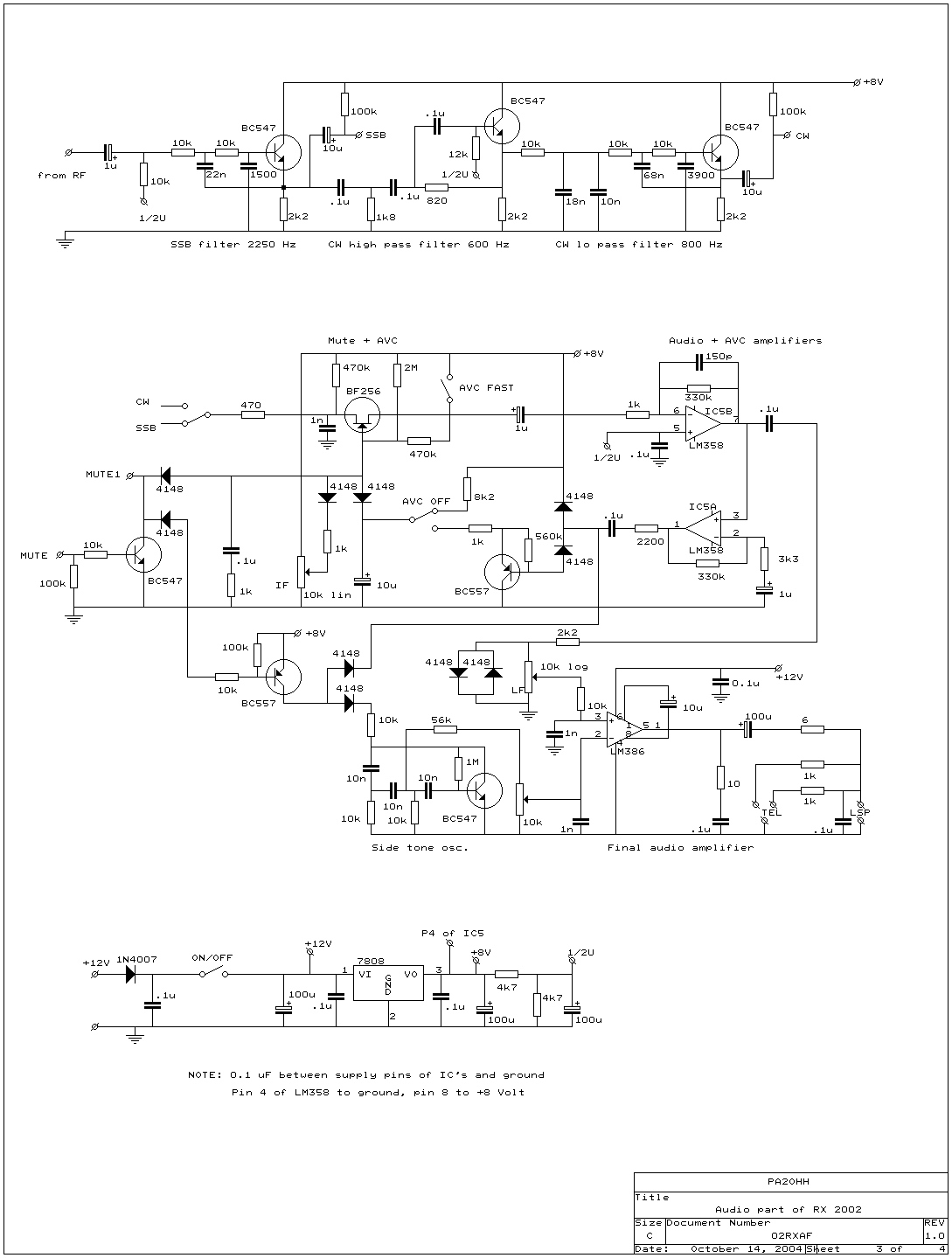
The audio part
AGC and low frequency amplifier
The BF256 fet takes care of the AGC (automatic gain control) and also mutes the audio during transmission. The receiver contains mute circuits here and there and a side tone circuit to use it together with a transmitter. Feel free to leave it out, I haven't even tried it myself yet and can therefore not guarantee it will work properly.
After the FET follows the first audio stage IC5B, the volume potentiometer with two anti-parallel limiting diodes and the power amplifier LM386. IC5A is the amplifier stage for the AGC signal with the audio detector behind it. The AGC does not work with weak signals. I think an advantage is that the receiver sounds much quieter and does not fill the room with noise when no signal is received. You can modify the behaviour by changing the gain of IC5A (changing the 330k resistor between pin 1 and 2). If the AGC "pops" very annoyingly, a resistor of 470 - 680k from the input (470 ohm, 470k ohm, fet, 1nF node) to mass can improve the performance. This will change the setpoint.
The IF potentiometer is located in the low-frequency section (after all, there is no IF amplifier stage), but its operation can be compared to that of the IF gain controller in a "normal" receiver.
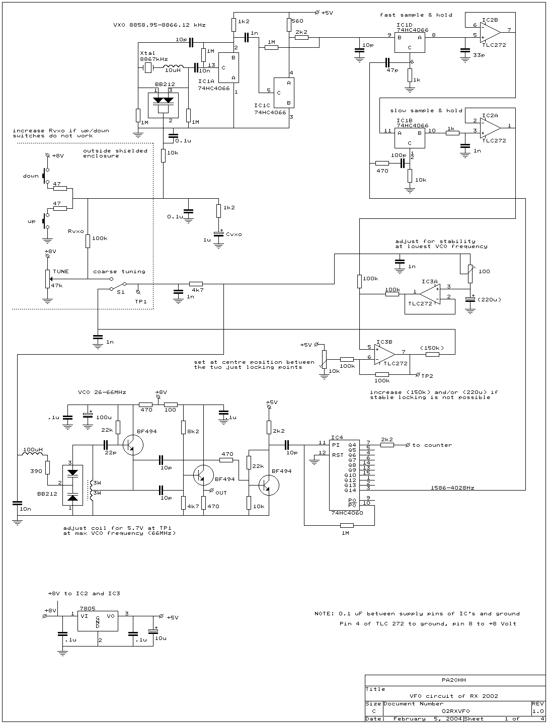
VFO
How does the VFO work?
Many small tuning ranges (23.6 kHz at 10 kHz and 52 kHz at 30 MHz) can be tuned with the 10 turn potentiometer. So you have an excellent band spread of 2.36 to 5.2 kHz per revolution! Press the up/down switches to go to the next small tuning range. For large frequency changes you must set S1 to coarse (coarse) and you can fine tune with the 10 turn potentiometer. Without this feature you would have to press the up key 1000 times to change the reception frequency from 10 kHz to 30 MHz!!
The system is based on a frequency lock circuit with a sampler, a VCO (Voltage Controlled Oscillator) and a VXO (Variable Xtal Oscillator). Harmonics from the (VCO/16384) are locked to the VXO. The frequency of the VXO is 8867 kHz but you can choose a different frequency. The frequency variation of the VXO is approximately 7 kHz. If you want to calculate a tuning range you can use the following formula:
(VXO frequency variation) x (VCO frequency) / (VXO frequency)
So you see that the size of the frequency band that can be tuned with the 10 turn potentiometer depends on the VCO frequency.
The maximum output frequency of IC4 (here 4028 Hz) must be significantly less than the 7 kHz VXO variation for proper operation.
You do not need measuring instruments to adjust the control loop resistance (the 100 ohm potentiometer), this can even be done better by ear rather than with measuring instruments! Tune the receiver to a strong and clean CW signal at a low frequency somewhere below 3 MHz. Adjust the 100 ohm resistor so that you hear a completely distortion-free signal without "noise". Very small noises were more audible than visible on the oscilloscope!
The Up/Down switches of the VFO
Just an important note: The UP switch only works if the VXO is tuned to a high frequency, i.e. in the upper part of the 7 kHz range. The reverse applies to the DOWN switch, which only works if the VXO is tuned to a low frequency.
When you press a switch, the control loop cannot follow the rapid frequency change and will lock onto the next harmonic relationship of the shared VCO signal and the VXO. When you release the switch, the VXO slowly returns to its frequency and now the control loop can follow this slow change.
Sometimes it happens that the VCO locks (not very stable) when there is a ripple voltage on the control loop. You can solve this with some DC offset by turning the 10k potentiometer a little.
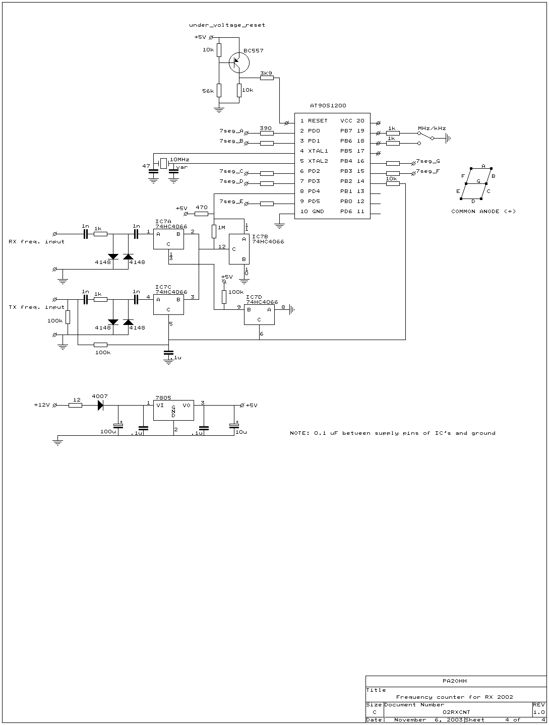
The frequency counter
"1" is displayed for 250 milliseconds.
" " display is off for 80 milliseconds.
"4" is displayed for 250 milliseconds.
" " display is off for 80 milliseconds.
"0" is displayed for 250 milliseconds.
And after a measurement time of 500 ms the "140" is shown again.
In kHz mode it will then display:
"6" is displayed for 250 milliseconds.
" " display is off for 80 milliseconds.
"2" is displayed for 250 milliseconds.
" " display is off for 80 milliseconds.
"3" is displayed for 250 milliseconds.
And after a measurement time of 500 ms the "623" is shown again.
The circuit with the 74HC4066 has been installed to also read the frequency of a transmitter. The transmitter is intended to apply a DC voltage to the TX input together with an HF signal, which switches the frequency counter. However, that transmitter is still a future project, the housing has been ready in the cupboard here for years....
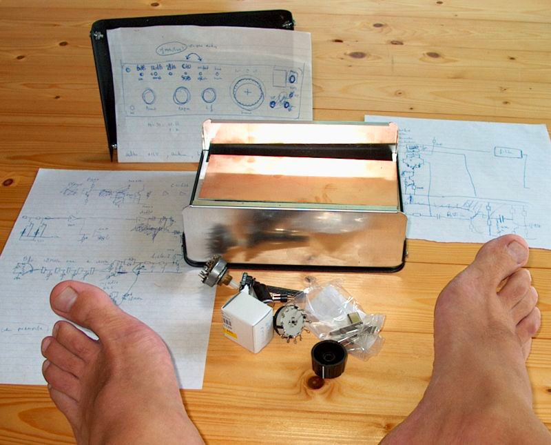
The start of the receiver project.
Sketches and some components. Will it ever work?
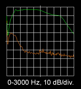 The SSB filter (green) and the suppressed sideband (orange). |
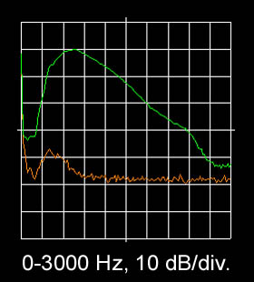 The CW filter (green) and the suppressed sideband (orange). |
Results
The receiver really works! Many enjoyable hours have been spent listening to this receiver. Although it is not as good as a real expensive commercial receiver, a lot of DX has been heard on all amateur bands. The selectivity and sensitivity are good, tuning is very comfortable. The CW and SSB filters work fine, the CW filter does not sound "narrow". The AGC also works well, although the control range is somewhat limited. With strong signals the HF attenuator must be used to get the signal within the AVRGC range.
Because the mixer is not very good, the HF generator must be used in the evening on 30 and 40 meters. But even with the maximum attenuation of 18 dB, the sensitivity on these bands is still sufficient. And the advantage is that your third intercept point also improves by 18 dB!
Of course there was also a mistake: the 56k and 10k resistors of the under-voltage circuit of the frequency counter were mixed up (the diagram is correct, but they are wrong in the photo). The result was that the EEprom values sometimes changed when the receiver was turned off.
| Frequency | 3525 kHz | 10125 kHz | 28125 kHz |
| Sensitivity (SSB) | -130 dBm | -131 dBm | -123 dBm |
| 3rd IP (-50 / -100 kHz) | -4.5 dBm | -10.5 dBm | +1.5 dBm |
| Supply current | 100 to 150 mA |
SOFTWARE FOR THE FREQUENCY COUNTER
"FREQRX02.ZIP" WITH "FREQRX02.ASM" TO PROGRAM THE FREQUENCY COUNTER
PHOTOS

Top view of the inside.
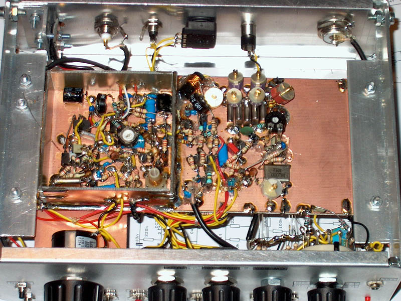
Bottom view of the inside.
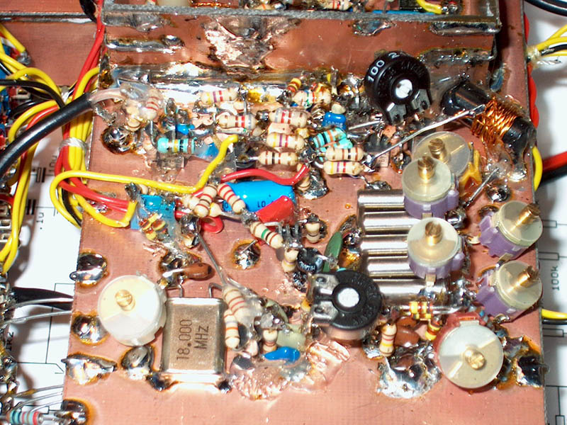
HF preamplifier, mixer with trifilar wound coil on a plastic shaft (No ferrite!)
ladder filter, BFO with Polyakov (RA3AAE) mixer, LF preamplifier
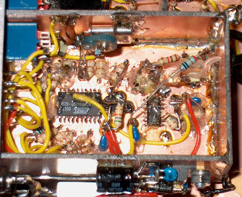
The frequency counter with SMD chips.
Before the chips were mounted, thin wires were soldered to the pins.
While soldering such a thin wire, the pin was separated from the adjacent pin with aluminum foil.
The SMD chips were glued to a piece of wood (from a match) that was glued to the PCB.
Pieces of a glue stick from a glue gun were used to glue on the resistors, etc.
(Melt the pieces with the soldering iron).
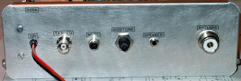
Rear view of the receiver