
One hour barefoot on the ice with the Portable Regenerative receiver was an exciting challenge!
But never try to do that when it is colder then -3C to -4C (26F)!
A PORTABLE REGENERATIVE RECEIVER
(2002)
KLIK HIER VOOR DE NEDERLANDSE VERSIE
One hour barefoot on the ice with the Portable Regenerative receiver was an exciting challenge!
But never try to do that when it is colder then -3C to -4C (26F)!
The regenerative receiver with tubes.
Once I had a regenerative receiver with a triode EC92 and a crystal telephone. It worked well on 80 meters but needed good ears and a long wire. And I always wondered why a radio amateur a few kilometers away from my QTH often thought that someone was tuning in on his frequency! Well what he heard was my oscillating 0V0 regenerative receiver....
If I should build such a receiver nowadays, it would not be used a lot and end its life quite soon in the junk box, together with the quite expensive tubes and transformer.

The reception with the regenerative portable receiver on the ice was great! Much better than indoors!
But the first 10 minutes were unbearably cold for my bare feet. After that my bare feet
with ice-cold red toes got used to the cold and then it was possible to walk barefoot on the ice!
Outdoors Short Wave Listening (SWL) activity with the portable regenerative receiver.
Of course you want to know what you can receive with such a receiver. Me too and I went outside a few times to see what could be heard during one hour.
CLICK HERE TO READ WHAT CAN BE HEARD WITH THE REGENERATIVE RECEIVER

After an hour barefoot on the ice, those toes were very cold and scary red!
But it was unbelievable how much could be heard with the simple regenerative receiver!
Realisation
Circuit diagram of version 1.1 with four transistors instead of five as version 1.0 had
RF preamplifier
T1 is the RF preamplifier and also a buffer between the regenerative circuit and antenna. RF level is controlled by a potentiometer. The telescopic antenna is adjustable between 20 and 40 cm.
The first version had an extra RF preamplifier between the antenna and potentiometer, but one RF stage and some extra AF gain gave less problems with strong RF signals. In this version, the potentiometer attenuates all signals directly at the input. It is possible to use even full size antenna's without overloading the first RF stage by increasing the RF attenuation.
Regenerative circuit, detector and reflex circuit
T2 is the most active transistor in this circuit. Firstly it act as an RF amplifier. The amplified signal is detected by two diodes and the detected audio is also amplified by T2. T2 is thus not only an RF amplifier but also an AF amplifier. Such a circuit is called a reflex circuit and was used a lot
when transistors were very expensive.
But T2 does more! It is also a regenerative circuit. Part of the RF output level is fed back to the input by the regenerative control potentiometer. Gain and selectivity increase enorm due to this regenerative process.
For AM reception the control is set to "just not oscillating". For SSB and CW it should just oscillate.
Oscillation can be controlled very smoothly, due to the negative voltage from the detector to the base when oscillation starts. Gain of T2 will be reduced by this negative voltage.
Automatic Volume and Selectivity Control
Indeed, there is automatic volume and selectivity control for AM reception in this simple circuit. When the signal level increases, gain of the transistor reduces due to the negative DC voltage from the detector. Due to the regenerative feedback principle, the gain of the total circuit varies considerably more than that of the BF494 transistor alone.
Also the selectivity changes. So if the station becomes weaker due to fading, the gain increases and also the selectivity. When the station becomes stronger, gain decreases and also selectivity, giving better reception quality of the higher audio frequencies.
Audio amplifier
T3 and T4 are BC547C transistors. Use the C type for more AF gain. Tone is controlled by a switch. There is also an audio output for a connection to the PC soundcard or external audio amplifier etc. If you want more audio level, simply connect the two earpieces of your headphone in series and replace the two 470 ohm resistors by one of 220 ohm.
Tuning circuit
The band switches create a rather comfortable tuning range of each band. But it is also possible to tune a whole shortwave band with very coarse tuning. Fine tuning for SSB and CW can be done by varying the regenerative control a little.
Adjust the values of the inductances and capacitors, number of switches to your variable capacitor and desired bands, it is not so critical. My 400 pF capacitor is in fact too much for the shortwave band 6 - 19 MHz, 200 pF is better, gives a higher Q.
Of course you do not need to use toroides, all kinds of coils are suitable.
L1 is wound around the toroide, L3 is at the cold (ground) side of L1, L2a + L2b at center position of L1. If regeneration does not occur or if noisy oscillation only happens with the 10k regeneration control at maximum, reverse the connections of L3.
Antenna
The receiver is very sensitive and you should expect that a lot of weak DX stations can be heard. But that is not the case. The receiver can only be used with short telescopic antennas, full size antenna's will cause a heavy overload of the receiver when the RF attenuator is not used.
Interference by strong FM broadcast transmitters
On a few locations, interference was caused by strong FM broadcast transmitters. This could be solved by connecting a 10 pF capacitor between the base and emitter and another 10 pF capacitor between collector and emitter of T1, the RF amplifier transistor. And the 100 ohm resistor at the base of T1 is increased to 330 ohm.
Notes
Built via the ugly method (dead bug method). Parts are soldered at one side of the print.
If you have too much regenerative feedback, place a resistor in series with the tickler coil L2a to the potentiometer.
I inserted a 10 ohm resistor after S1 (power switch) as a kind of fuse. And of course, the external power supply is really unnecessary for a supply current of only 2 mA!

An hour barefoot on the ice with the portable RX was fun, I should do that much more often!
And much longer! Often even a few hours barefoot on the ice! That was intens, challenging and funny!
But never try that when it is colder than -3C to -4C (26F)!
PHOTOGRAPHS

Front view and ice cold bare feet on the ice!

Frequency bands, side view and ice cold bare feet on the ice!

Slowly warming toes!
PERFORMANCE
A lot of hours have already been spent with listening to this receiver with pleasure! Considering that it is a very simple receiver with very low battery consumption and that a telescopic antenna of 40 cm at floor level is more a dummy load than a DX antenna, it performs good. But do not compare it with a good receiver plus antenna. It is not good enough for reception of weak signals, only stations of average strength can be heard.
Oscillator level at antenna input: Maximal -68 dBm measured at 19 MHz, that is 11 dB lower than the official limit for receivers.
Sensitivity: CW signals of -130 dBm (0.05 uV) are readable on all shortwave bands.
Supply current: 2 mA at 6 volt.
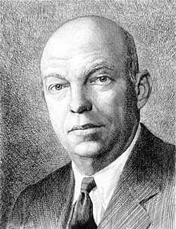
Edwin Armstrong who invented the regenerative radio in 1912.
ACTIVITIES WITH THE REGENERATIVE RECEIVER
Interference sources
Within a few minutes, two interference sources were located in the shack, an electronic lamp and the PC plus monitor, even if they were switched off. The interference disappeared when the mains plugs were disconnected. One day later the satellite dish receiver was located as 80 meter interferer.
Adjustment of oscillators
Adjustment of oscillators of the frequency counters are easy with this receiver, just zero beat the oscillator signal with the reference frequency source at 10 MHz.
Radio repair
The local oscillator signals of broadcast radio's and the 455 kHz and 10.7 MHz IF signals can be monitored by the regenerative receiver.
EXPLANATION OF THE REGENERATIVE PRINCIPLE
Increase of the gain
Maximum gain if the regenerative control is set to
"just oscillate" or "just not oscillate" position.
Increase of the selectivity
Maximum selectivity too if the regenerative control is set to
"just oscillate" or "just not oscillate" position.