SWR METER FOR QRP USE
(2001)
KLIK HIER VOOR DE NEDERLANDSE VERSIE
SWR meters for QRP portable use.
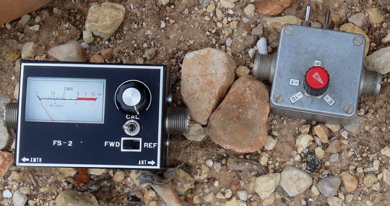
SWR meter for QRP use!
My SWR meter needed quite a lot of power to measure the SWR, especially on 80 meters. That was no problem in the shack, there is always a transceiver that can generate this power. But I needed to have a SWR meter that I could take with me while working portable in nature with an extendable dipole. It had to be robust and to be possible to measure the SWR with QRP power. I made two versions. One with a moving coil meter indication and one with a LED indicator. The moving coil meter was better but less robust than the version with the LED. This type of SWR meter has a number of advantages. During the measurement, the load of the output stage is at least 33 ohms and maximal 100 ohms. Therefore, the transmitter output stage cannot be damaged by extreme mismatches. And you can also use the meter as a dummy load. During the measurement, the emitted power is only 25% of the normal transmit power. If you want to experiment with a quarter of the transmit power during working QRP, then you put the meter in measurement mode SWR + REF.

Left the principle of the forward measurement, right the principle of the reflected measurement.
operating principle
The measurement is based on the Wheatstone bridge. At the left you can see the principle of the forward measurement or the calibration mode. During this measurement, the antenna is replaced by a resistor of 50 ohms. The power is measured across one of the resistors and the meter is set to full scale. At the right you can see the principle of the reflected measurement. The resistor of 50 ohms of the bridge is now replaced by the antenna. When the antenna is exactly 50 ohms, there will be no voltage present across the meter, as the bridge is in equilibrium.
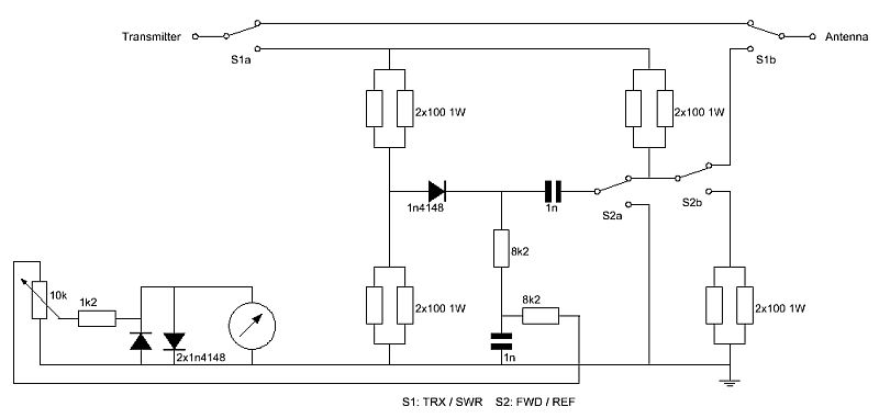
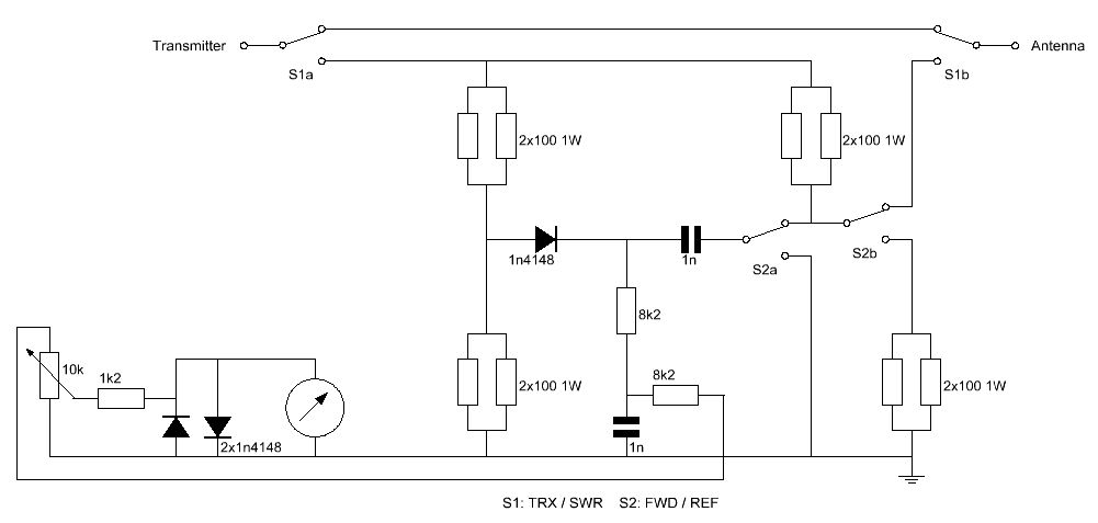
Diagram of the SWR meter with a moving coil meter as an indication.
big diagram
Description
At a flea market a SWR meter for the 27 MHz band was bought. It was in good condition and so I had already the connectors, meter with scale and control knob. Only the switch S1 had to be built-in, just above the existing switch S2. All the original components have been removed and replaced by new components as given in the diagram.
During transmission, the switch S1 is in the position TRX and the bridge is not used. When adjusting the antenna, S1 is set to the position SWR. When the switch S2 is in the shown position REF, the RF voltage is measured between the two halves of the bridge. When the antenna impedance is exactly 50 ohms, the measured voltage is zero. When we set the switch S2 in the FWD position, the RF voltage across the 50 ohm resistance at the bottom left is measured. The switch S2b replaces the antenna by a resistor of 50 ohms. The resistor of 50 ohms of the bridge were made by two resistors of 100 ohms - 1 watt in parallel. So the bridge can dissipate 8 watts, enough for our QRP transmitters.
After the diode detector you can find a 8k2 ohm resistor and a capacitor of 1 nF. This is a low pass filter for filtering out the RF component. The subsequent 8k2 resistor does reduce the control range of the potentiometer. By means of the 10k potentiometer, the meter is adjusted to full scale in the FWD position. The two diodes in parallel with the meter limit the voltage across the meter up to � 0.6 volts, and are intended to protect the meter against too large peaks. One of the two diodes is unnecessary, as we do use only positive voltages.
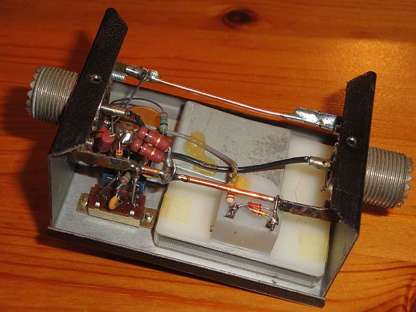
The inside.
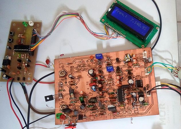
A nice Barefoot Power DSB transceiver for 40 meters, the Uirapuru made by Andre.
See the website of PY2OHH (http://py2ohh.w2c.com.br/trx/uirapuru/uirapuru.htm)

The second version with a LED as indicator.
The second version with a LED as indicator.
But such a meter with a needle is a fragile thing. Therefore, a second version has been made with a LED as an indication. A real decent thing! But not as accurate as a moving-coil meter. And difficult to read in sunlight. But still a good thing to tune the extendable dipole.

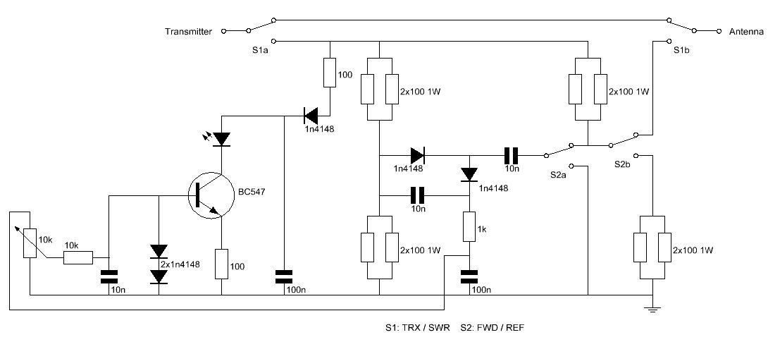
Diagram of the second version of the SWR meter with a LED as indicator.
big diagram
Description
The measuring bridge is the same as the version with the moving coil meter, see above.
For the diode detector, a slightly different circuit is applied, one that doubles the voltage, as for the LED a little more voltage was desirable. After the diode detector you can see a resistor of 1k ohm and a capacitor of 100 nF. This is a low pass filter for filtering out the RF component. Then follows the potentiometer and the 10k resistor with 10nF capacitor ensures that the transistor and diodes will not detect RF. The two series-connected diodes 1N4148 to the base of the transistor ensure that the voltage on the base is limited to �1.4 volts. The base-emitter voltage is 0.7 volts. Thus the voltage across the emitter resistor of 100 ohm is maximal 0.7 volt and maximal 7 mA can flow through the LED. With the 10k potentiometer and in the FWD powition, the meter is adjusted so that the LED hardly increases in brightness. That is the mentioned 1.4 volt point. Read the power on the indication of the potentiometer and you know approximately the transmit power of your QRP transmitter. The transistor circuit is supplied from the rectified voltage of the RF transmitter. The applied LED needed a lot of current. Newer LEDs do need much less current, so you can choose a higher value for the 100 ohm emitter resistor (560 ohms or so).

The inside. Glue, solder, no printed circuit board.
The extendable dipole antenna
An extendable binary dipole was made. There were pieces of wire of 10cm, 20cm, 40cm, 80cm, 160cm, 320cm and 640cm for each dipole leg. By connecting the desired wire lengths, you can tune the antenna to any desired shortwave frequency. The wire ran through tabs in a nylon wire high in the air. The end was attached with a plastic clip to the nylon wire. It worked, but the hassle with all of these wires in a plastic bag was not a success. So I did not use it anymore and made three dipole antennas, one per band, 40 meter, 30 meters and 20 meters. That worked better.
BACK TO INDEX PA2OHH