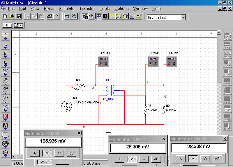
To get some insight in the use of transformers let's put together the following circuit:
Some remarks.
Arbitrarily I choose for rf-transformer RF2. The AC-voltage source is set up for
1 V RMS, so Vtt is 1.41 V. That is because the multimeters display RMS-voltage
rather than Vtt.
Let's try AC-analysis first to get some insight.
Let's sweep from 1MHz to 1GHz and let's plot the voltage at node 3, that is the voltage across R3.
The voltage aross R3 starts at 10 mV and from 100 MHz remains constant. The phase starts a 90 degrees, pure inductive behaviour, and then remains at 180 degrees. So, this rf-transformer can be used from about 100 MHz.
I will set the frequency of the AC-voltage source to 100 MHz and perform some measurements.
This reveals that the voltage across the primary of the transformer is 183.935 mV and across the output resistors both 28.308 mV. Dividing these two voltages 183.935/28.308=6.498. So the turns ratio is 6.5:1.
PA1KDG, june 2003