To get into the ether I need a QRP-cw-transmitter. I have some power mosfets IRF840 and some BC174B transistors. Let's try to make a 5 W QRP-transmitter from these components. First we will play with a driver stage using an ordinary NPN-BJT (bipolar junction transistor). Lets first investigate what this stage can deliver. Then we will concentrate upon the output stage with a power-MOSFET.
I want to simulate what I can expect from a BC174B npn transistor. I have some of them in my junkbox.
Unfortunately I can't find this transistor in the database of Multisim. So I have to find the SPICE model of this transistor on the internet and add it to Multisim's database.
Using google with BC174B as search argument I find the following information:
http://xedox.de/transistor2.htm
| Bezeichnung | Gehäuse | Typ | Ptot | Ucbo | Icmax | hfe | MHz |
| BC174B | TO-92 | NPN | 0,3W | 70V | 0,1A | 240-500 | 250 |
This is promising for a cw-xmtr at 3.5 MHz.
Let's try Philips for the SPICE-data of this transistor.
nothing...
Is there a transistor in Multism that looks like the BC174B?
| Bezeichnung | Gehäuse | Typ | Ptot | Ucbo | Icmax | hfe | MHz |
| BC182B | TO-92 | NPN | 0,3W | 60V | 0,2A | 240-500 | 280 |
Ok, let's try the BC182B for the simulation.
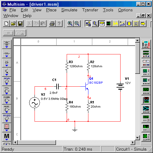
Suppose Ic=50 mA and Vcc=13.8 V. With 1 V on the emittor, we need an emittor-resistance of 20 ohm. The remaining supply-voltage of 13.8 - 1 = 12.8 V will be evenly divided between the collector resistor and the transistor itself. So we need 6.4 V across the collector-resistor. So the value of this resistor must be 6.4 V / 50 mA = 128 ohm. The gain with these values is Rc/Re = 128 / 20 = 6.4. The voltage on the base is about 0.7 V higher than the emittor-voltage. So we need a bias network that provides 1.7 V. The upper resistor should be about 10 times the collector resistor. So we take 1280 ohm. The voltage across this resistor will be 13.8 - 1.7 = 12.1 V. So the lower resistor must be (1.7/12.1)*1280 = 180 ohm.
Finally we add a capacitor at the input. The impedance of this capacitor must be about 10 times less than the lower bias resistor, so 1/wC must be 18 ohm at 3.5 MHz. So C= 1/(2*pi*f*18). Then C=2.5 nF.
For our first simulation we connect an ac-source with 0.5V tt and a frequency of 3.5 MHz. Later we will add an oscilloscope to verify our design.
Let find out what Multisim thinks about this design!
We will choose virtual components, they are easier to manipulate. In the final design phase they can be replaced by real components with values from the E12-series for example.

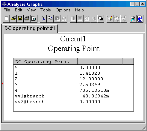
Let's check the dc-operating conditions by simulate/analysis/DC-operating point:

What is the meaning of above output?
In the first column are the various nodes in the schematic. The second has the various voltages and currents. We can see that the circuit draws about 43 mA.
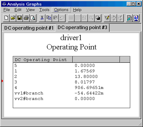
Node 1 is the base of the transistor and the voltage is 1.46028 volts. Node 2 is the supply and I forgot to put the supply voltage at 13.8 V. I used the default 12 V instead!

As you can see, this was changed easily! The simulation is in accordance with our calculations.
In order to measure the internal resistance of the amplifier stage (I don't know how to calculate this from the circuit) we connect a load resistor of 100 ohm. In order to preserve the DC operating point we will connect a capacitor of 0.1 µF. This capacitor has an impedance of roughly 0.5 ohm at 3.5 MHz. We will measure the value of the ac collector voltage with and without this load. From this measurement we should be able to determine the internal resistance of the amplifier section.

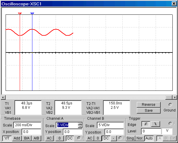
On the oscilloscope we see:

The output voltage is 2.5 Vtt (voltage top-top) when the amplifier is loaded with 100 ohm. When we disconnect the load resistance we measure 5.7 Vtt. So the open source voltage is 5.7 Vtt and 5.7-2.5=3.2 Vtt is lost across the internal resistance of our amplifier. Now we can calculate this internal resistance. With the same current flowing through the internal resistance and the load we can conclude that this internal resistance has a value of (3.2/2.5)*100 ohm = 128 ohm. And that is exactly the value of the collector resistance!
That sounds logical because the transistor may be considered as a current source with a corresponding high internal resistance.
PA1KDG, june-2003