After succeeding in passing the Morse test I would like to make my first cw-qso on 80 m. I have a receiver, a Kenwood TH-F7E, but no transmitter yet. Looking in my junk box there are some IRF840 MOS-FETs staring at me. Let's try design a final stage that will deliver 5 W QRP-cw at 3.5 MHz. Before taking a solder-iron it might be worthwhile to do some experiments and measurements on the computer. Multisim is a software tool that helps a lot to get a working design.
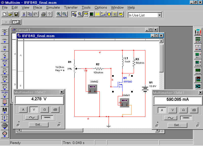
I am very pleased to find the IRF840 in Multisim's database. As a first test I come up with the following circuit:
A potentiometer R1 is used to bias the MOSFET. This potentiometer will later be replaced by a suitably uncoupled circuit with a zenerdiode . As a first setpoint I decide to go for a DC-current of 0.5 A from drain to source. Then the current can be swung between 0 and 1 A. Then it must be possible to get at least 5 W of power out of this circuit.
The potentiometer can be 'turned' by pressing a or A on the keyboard while in simulation mode. As you can see with a bias of 4.278 V the IDS is 590 mA.
In order to get insight in the demands of the driver stage I connect an AC-voltage source at the gate of the MOSFET. To preserve the bias-voltage I use a capacitor of 0.1 µF in series. The impedance of this capacitor is 1/(2*pi*f*C) = 0.5 ohm at 3.5 MHz.
The multimeters can be removed and an oscilloscope is added to view the signal at the drain of the MOSFET. In order to see the drive current a multimeter is added in series with the driver-source:
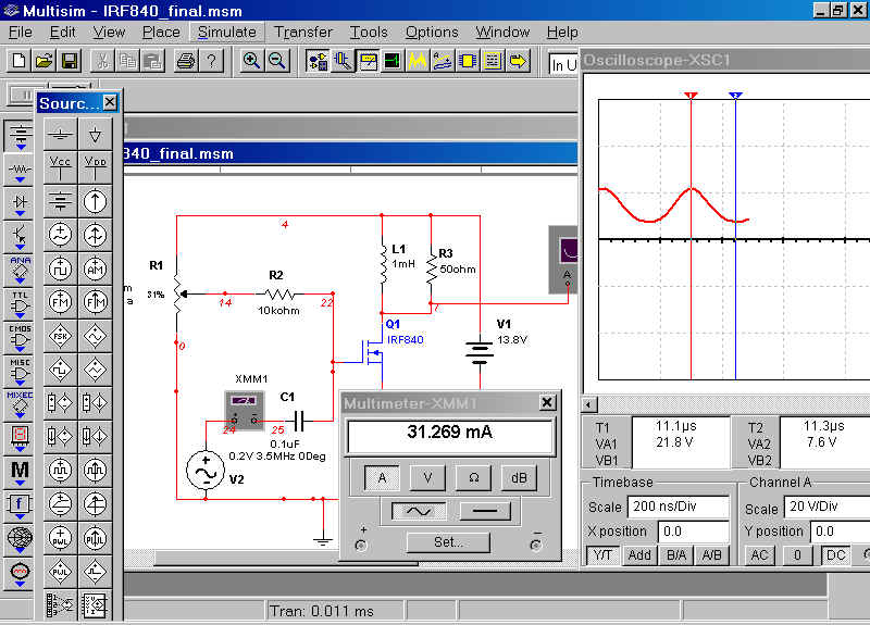
From this first simulation you can already draw a lot of conclusions.
The output power can be calculated as follows: Vtt across the 50 ohm load resistor is 21.8-7.6 = 14.2 V. The rms-value is 0.5*0.7*14.2 = 5 V. So the power delivered to the load is U2/R=52/50 = 0.5 W. If the load was connected using a step-up transformer the load a seen by the MOSFET could be reduced to say 12.5 ohm. Then the power would be 2 W.
This looks promising. What about the dissipation in the power fet itself? As a first approximation you can say that the average DC-current is 1A and the average voltage is 7.1 V. So about 7 W will be radiated by the MOSFET in the form of heat. Appropriate cooling is required!
What about the drive demands? The voltage source is 0.14 V rms and has to deliver about 31 mA. So the driver sees an impedance of 0.14 / 0.031 = 4.5 ohm. With a coupling transformer one might use about 1.4 V into 50 ohm, about 40 mW.
PA1KDG, june-2003