Looking for schematics for a transmitter using a MOSFET I stumbled upon class E. Class E is a mode in which the amplifying element, a BJT or a MOSFET, acts like a switch. The dissipation in the transistor is very low and the efficiency can be as high a 90%. That sounds promising for my QRP-transmitter!
On http://www.circuitsage.com/lnapa/classe.pdf I found a lot of formulas. After some calculations I came up with the following scheme. Of course I did some experimentation with Multisim. Virtual experimentation gives a lot of insight, saves a lot of time and it is safe!
This circuit delivers about 50 Vtt into 25 ohm. That is (0.7*50)2/25=49 W. With 30 V supply instead of 60 V I get 22.9 Vtt, good for about 10 W.
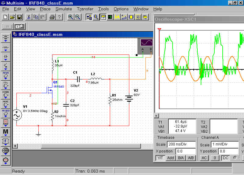
A few remarks about the Multisim setup. I placed a resistance of 1 milli-ohm in series with the source connection of the MOSFET to be able to measure the drain-source-current. Furthermore I coloured the line to the oscilloscope green to distinguish it from the red voltage. WIth the scale set to 1 mV/div every div is 1A.
The oscilloscope diagram above shows in green the current through the MOSFET and the voltage on the drain. As you can see there is not much dissipation in the MOSFET because either the voltage across the MOSFET is high and the current almost zero or the current is high but the voltage across the MOSFET almost zero. Note that there is almost 80 V on the drain, even with a supply voltage of only 30 V!
Now a lot of experiments can be done. For example leave C2 and look what happens to the voltage on the drain. This voltage now exceeds 200 V! Still with only 30 V supply voltage. About 17 W will be delivered to the load resistance in this case. The maximum current through the MOSFET is slightly more than 2 A. No problem for an IRF840. The supply current is 614 mA, this can be measured by putting a multimeter in series with the battery as you would do in real life. This means 18.4 W DC. Only 1.4 W is wasted in the MOSFET!
C1 can be replaced by a variable capacitor with a value twice as big and set to 50%. Then you can fine tune the circuit during a simulation run and see immediate results. Again like in real life!
It is also possible to connect a second oscilloscope to look at more signals simultaneously. Also it migh be handy to connect a multimeter across the load resistance. That helps in estimating the output power of the circuit. Note that this multimeter will directly display the RMS-value of the output AC-voltage.
PA1KDG, june 2003