Experiment with a
Gray-counter in VHDL
What is a Gray-counter?
A counter
that outputs Gray-code instead of straight binary
What is Gray-code?
Gray-code
is used for optical and mechanical encoders. In the Gray-code
only one bit at a time changes for adjacent codes.
Take a look
at http://www.ida.net/users/tetonsl/railroad/graycode.htm
for a very nice picture.
Example
Binary:
|
0 |
1 |
2 |
3 |
4 |
5 |
6 |
7 |
|
000 |
001 |
010 |
011 |
100 |
101 |
110 |
111 |
Gray:
|
0 |
1 |
2 |
3 |
4 |
5 |
6 |
7 |
|
000 |
001 |
011 |
010 |
110 |
111 |
101 |
100 |
In binary
code more than 1 bit can change at any moment. Eg. If you go from 5 to 6
the code changes from 101 to 110, the last two bits change simultaneously.
In the
Gray-code there is only 1 bit that changes from 0 to 1 or from 1 to 0.
How can I construct
Gray-code on paper?
Reference: http://www.nist.gov/dads/HTML/graycode.html
One
approach is as follows:
Write down
a 1 bit Gray-code:
0 1
Now append
the same code in reversed order:
0 1 1 0
Prefix the
first half of the series with a zero:
00 01 1 0
And the
second half with a one:
00 01 11 10
Hurray! You
just created a two bit Gray-code!
Now for a
three bit code;
00 01 11 10
00 01 11 10
10 11 01 00
000 001 011
010 10 11 01 00
000 001 011
010 110 111 101 100
How can I program
Gray-code?
From http://remus.rutgers.edu/~rhoads/Code/code.html
some snippets of C-code:
unsigned
long bin_to_gray( unsigned long n )
{
return (n ^
(n>>1));
}
/* assumes
32 bit integers */
unsigned
long gray_to_int( unsigned long n )
{
n ^= n>>1;
n ^= n>>2;
n ^= n>>4;
n ^= n>>8;
n ^= n>>16;
return n;
}
Let’s try to
convert 0101 from binary to Gray using the upper function bin_to_gray:
n = 0101
n>>1
is n shifted one position to the right:
n>>1 0010
^ means exor, so delivers a one where left and right operand
differ
0101 ^ 0010
0101
bitwise exor 0010 = 0111
let’s try
them all
|
code |
n |
n >> 1 |
N ^ (n >> 1) |
|
000 |
000 |
000 |
000 |
|
001 |
001 |
000 |
001 |
|
010 |
010 |
001 |
011 |
|
011 |
011 |
001 |
010 |
|
100 |
100 |
010 |
110 |
|
101 |
101 |
010 |
111 |
|
110 |
110 |
011 |
101 |
|
111 |
111 |
011 |
100 |
The last
collomn above is exactly similar to the Gray code constructed earlier.
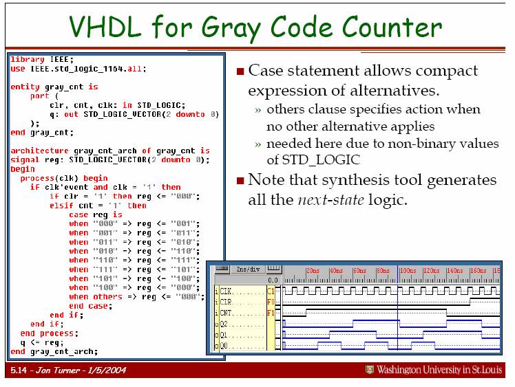
How can I construct
Gray-code with VHDL?
Perhaps the
simplest way for a small Gray-counter is with a case-statement.
I found the
following snippet from Jon Turner (http://www.arl.wustl.edu/~jst/cse/260/lec/chap5.pdf)
Implementation with ISE
Startup
Xilinx the Project navigator (I use version 6.2.02i).
Close the current project and select a new project.
Give directory and name of your top level HDL-file.
Select New Source / VHDL module
Define clr, cnt and clk as in
and define q as out with MSB 2, LSB automagically becomes 0.
Next, Finish, Next, Finish and ok, I get my VHDL template:
library IEEE;
use IEEE.STD_LOGIC_1164.ALL;
use IEEE.STD_LOGIC_ARITH.ALL;
use IEEE.STD_LOGIC_UNSIGNED.ALL;
-- Uncomment the
following lines to use the declarations that are
-- provided for
instantiating Xilinx primitive components.
--library UNISIM;
--use UNISIM.VComponents.all;
entity gray is
Port (clr : in std_logic;
cnt : in std_logic;
clk : in std_logic;
q : out std_logic_vector(2 downto 0));
end gray;
architecture Behavioral of
gray is
begin
end Behavioral;
It is now a
matter of editing this template so that it looks exactly as the slide of Jon
Turner above, save, check and run the simulator.
In the
Xilinc Project navigator screen middle left there is a pane called “processes
for source ”gray-behavioral””.
There are 5
topics:
- Add
Existing Source
- Create
New Source
- Design
Entry Utilities
- User Constraints
- Implement
Design
The last
topic “Implement Design” has a topic “Synthesize – XST” which has a sub-topic
“Check Syntax” .
Double-click
on “Check Syntax” and correct erors, save your work, check syntax until
everything is fine.
Now you
have a green check-mark.
Now it is
time for a simulation!
Double-click
on “Launch Modelsim Simulator”.
We see
several windows. The most interesting window perhaps is “wave - default”
because there we see the signals as on an oscilloscope or logic analyser. However
all the signals are U, undefined. We have to define a
test-bench to define the input-signals for out design.
In the
project navigator in the left upper window called “Sources in Project” click on file
called “gray-behavioral”.
Now
double-click on “Create New Source” in the window left under.
Choose VHDL
test bench waveform and name it “gray-test-bench”.
Next, next,
finish takes you to an other window where you can
define the test signals.
Click on
the blue pads and make clr 1 during two clock periods.
Double
click on cnt and select a random pattern, select “do
it for 50 cycles” and count every 4, now click ok.
Save your
test wave form. Always do a save whenever you changed something.
Double-click
on “Simulate Behavioral VHD Model”.
Now the
simulator starts up.
The most
interesting pane is “wave – default”. Perhaps you have to zoom out to see the
logic signals.
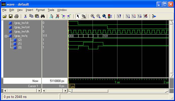
In the diagram above you can see that our Gray-counter counts according to the
gray-code if the signal cnt = ‘1’ and that is exactly what we have programmed
in the defining VHDL-program!
Universal Gray-counter
n-wide
Ref: http://www.isibrno.cz/~ivovi/gray_counter.pdf
Wageningen,