The making of a dipole antenna for HF
a June 2007 story
Impressions of the plans, the ideas, the construction and the installation
Note (March 2021): As we moved from the polder to Haarlem.... this antenna does no longer exist.
The current HF Antenna (High End Fed) will be replaced in time by such Open Dipole with symmetrical feed line
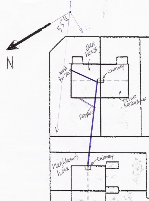
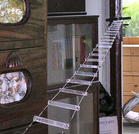
| Some historical facts: Being a HAM since 1974 (and of course also in the years preceeding those....) there has always been interest in the use of antennas. On my current QTH Vijfhuizen, there is room for a longer wire antenna. In the past I used an end fed wire of around 25 meters, but the construction was brought down by the impact of time and weather. I had to look for something else, as the temporary antenna (that now hangs for almost 18 months) picks up too much manmade noise. The result of the literature study, the tips I received from other hams, and the available space I have around our house, gave me the conclusion that an open dipole with a symmetrical feeder was the ultimate solution for the location. Suddenly being in the possession of an MFJ-941D "Versa Tuner II" (having the balanced output) was a great attributor to that final conclusion. With respect to the place: on the picture (right) you'll see a view from above. We lived in a two-under-one-roof house. The neighbours 'at the bottom' allowed me to attach the antenna to her chimney. They already allowed that attachpoint some 9 years ago, when I installed that end-fed wire between their and our chimney. The dipole runs in a 307 degrees azimuth, so almost North West. One half of the full dipole (the northern part) is straight and free from ground, the other half goes from the feeder to the chimney, and then attaches to the mast for my V2000 Diamond antenna, so it is bent approximately halfway. |
 This
was the plan, and this is how it was done!
|
||||||||||||||||||||||||||||||||||||||||||||||||||||||||||||||||||||||
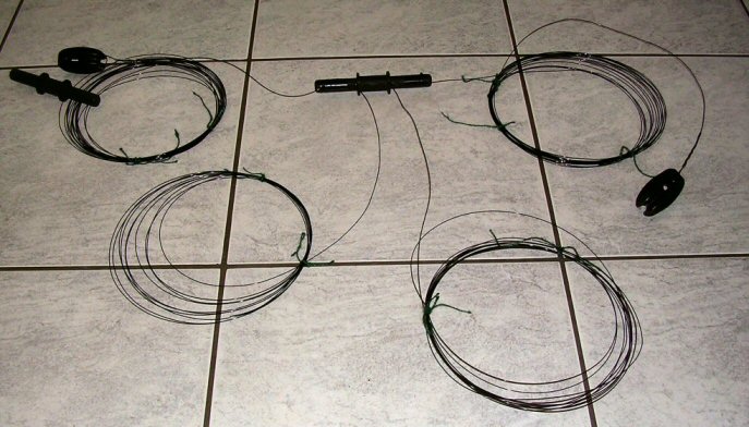 The wires are of the same length, and each half is of one piece, making adjustments possible |
The construction of the
antenna: The choise of wire was simple. In an RSGB publication entitled "Practical Wire Antenna's" by John D. Heys, G3BDQ, a comparison is made between a number of antenna wire types. His verdict is, that solid wire has preference over multiple, twisted wire for the sake of service life: solid wire has preference, as it holds better in time. A friend, Carlo PE1MWL, suggested to use the so called DX-wire (P. Bogner Antennetechnik, www.DX-WIRE.de), a steel wire with a thick copperclad layer, and yet only 1mm thick. And so I did. He gave me the roll, and told me to take whatever I needed. Not even 50 meters! After some encouageing from my side he allowes me to trade it in against a 'good bottle of wine'. Carlo, being a wineshop owner, will be a critical receiver...... |
||||||||||||||||||||||||||||||||||||||||||||||||||||||||||||||||||||||
| For the insulating parts (centerpiece and end insulators) I
used parts that I already had in my posession from earlier activities.
I think that I would have used PVC (electrical pipe) parts otherwise.
But I was lucky with these parts collecting dust. As stated earlier: feeder and (half) dipole are one piece of single wire, enabling me to make the best fitting dipole. I 'guessed' the length to be about 2 times 14 meters something, but it finally turned out that could put away 27 meters in total, so 13.5 meters per dipole half. The feeder will then be 8m50. The DX-wire is very stubborn when it comes to retaining it's original shape. This makes the wire difficult to handle during the construction process. Especially for the installation of the specers, three people are needed on the job to get that fixed. |
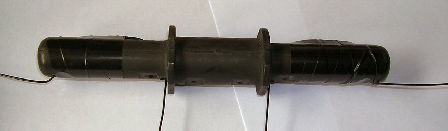 the center piece 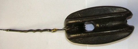 the end insulator |
||||||||||||||||||||||||||||||||||||||||||||||||||||||||||||||||||||||
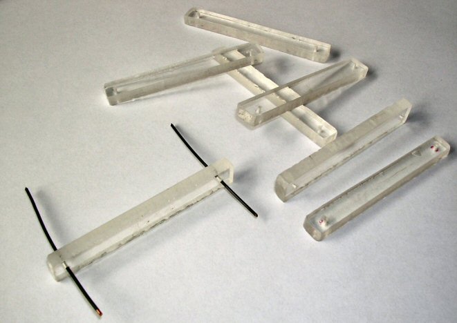 The collection of spacers, all (approximately) the same size, with the drilled holes near the edge. 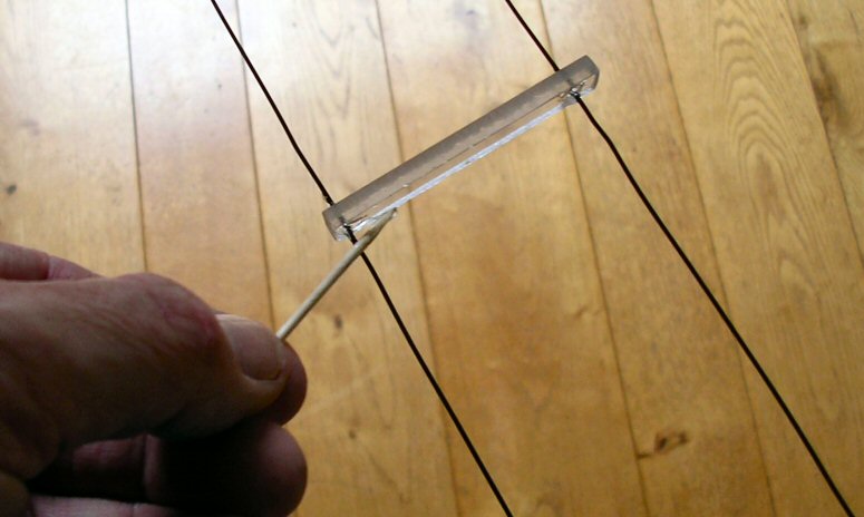 |
Making and installing the
spacers: Although my XYL will not agree, I don't throw away things that can be 'handy in future'. That helped for the construction of the spacers for the feeder line. From a (twenty?) years old piece of plexyglass, I sew some 36 spacers (65mm x 9mm, 4 mm thick) with 1mm holes spaced at 55mm. This was a pretty straight forward job. The holes were drilled by another friend and SWL Steven. On the left are the details: Impedance: Z=276.log 2S/d, where S is the distance between the feeders and d is the diameter of the wire, both in the same dimension. This gives an impedance of 563 Ω. After the provisionally installtion of the spacers, the antenna was tested on our remote test site in Zandvoort, where we also installed those spacers. A very good result: tunable on all HF-bands. Then the antenna was packed and taken to out house. I used one Saturday morning to make the antenna ready for installation by installing the mounting parts at the end, and glueing in the spacers. This I did with two-component adhesive. (picture left) after putting the feeders on tension (using room door handles as attachpoints) and sliding the spacers at about 30 cm, the adhesive was applied |
||||||||||||||||||||||||||||||||||||||||||||||||||||||||||||||||||||||
 |
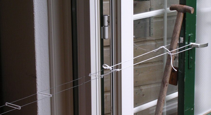 The assembled feeder lines, after they were put on tension and the adhesive was applied On the left: attaching the far end on the door from the hall to the living room. Above: the near end, with the shovel to adjust the tension. |
||||||||||||||||||||||||||||||||||||||||||||||||||||||||||||||||||||||
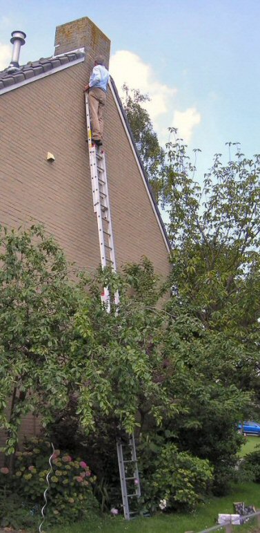
| The installation process: First of all: this would never have succeeded without the great support that I received from Steven. He constructed a ladder that reached to 9 meters heigth for the far end installation, on the chimney of our neighbour's house. 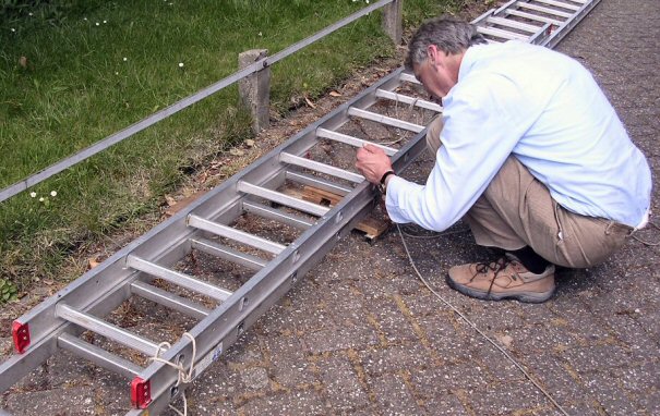 On the picture here above you'll see him attching the rope to the two parts, and (after we raised it) climbing it to attach the antenna. This is the picture on the right. But don't get confused and don't believe that the ladder construction is not safe. Because an additional stabiliser rod is installe at the bottom, and a safety rope is used at the high end. For reference: if you look to the most above picture, this is the lowest part (chimney - neighbour's house) It went surprisingly quick, this part. After that, bringing the antenna to our garden, and raising it to our roof, was more troublesome, as we had to navigate a hardly invisible wire between the trees in my backyard. But finally that was fixed as well (using small ladders and a long pole. 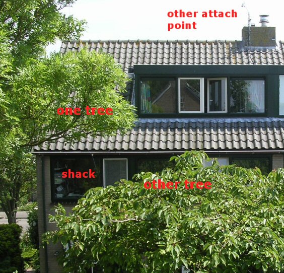 |
 on the picture to the left: The viewpoint here is on the ladder against the house of our neighbours, looking towards our backyard and aftside of our house. From this point the antenna will be attached to the 'other attach point', and the run over the roof to the foreside of the house You also see the location of the shack. The feeder will end up here. |
||||||||||||||||||||||||||||||||||||||||||||||||||||||||||||||||||||||
| Completing the job: To finalise the story, here are some pictures and descriptions of the details of the attachments. First the farrest end: on the mast for my two 'combi' V2000 antenna: 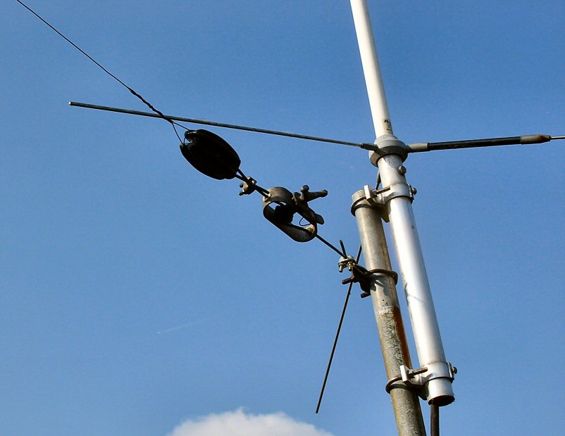 Shown here, with the adjuster turned up, the antenna length is really at the maximum. From this location, and looking to the chimney, you see the bend in this half of the dipole: 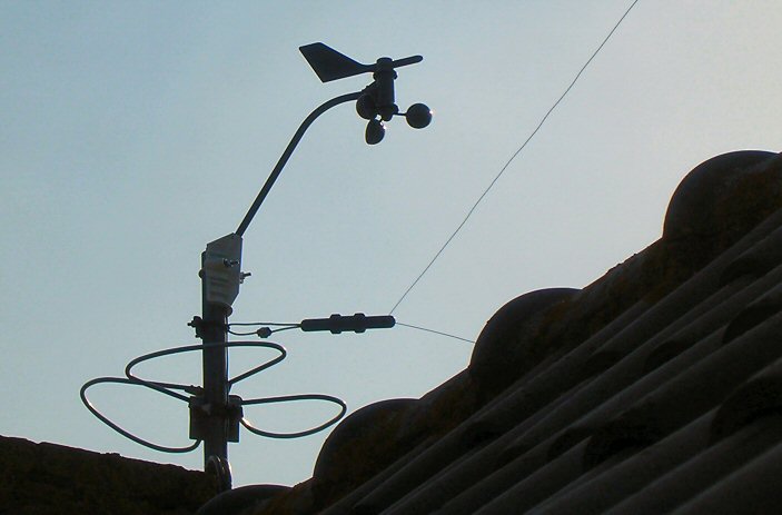 As can be seen: I had one spare center piece, and that is used at the bend. Also on this picture the wind vane for speed and direction information to my weatherstation. On the picture to the right it shows how it looks from the roof. The picture was taken from the flat roof of the dormer extension. It is the attick of the house where my older QRP has his quartes |
To get an idea about that V2000 antenna, of which I used the
mast to attach the dipole (picture left), here is a picture that I
retrieved from the archives. On it the dipole attachment is (thus) not
visible: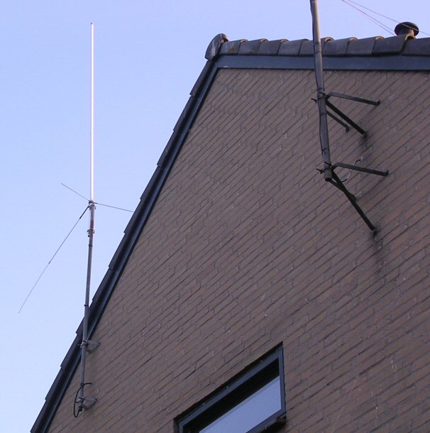 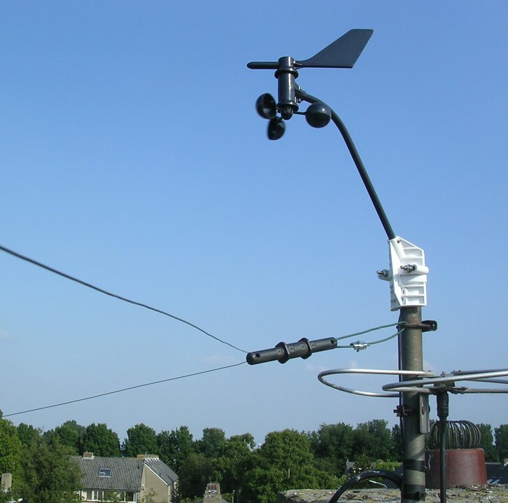 |
||||||||||||||||||||||||||||||||||||||||||||||||||||||||||||||||||||||
Finally some words on the tuner. I had the intention to make an antenna tuner for the feeding of that symmetrical feeder. But suddenly I was in the opportunity to acquire an MFJ VERSA TUNER II (model MFJ-941D). This does not mean that I will never construct one myself, but for the moment this part suits me well. I made on overvoew of the "tuneability" of the new antenna, and there are no hick-ups. In the earlier mentioned "Practical Wire Antenna's" by John D. Heys, the is a table with 'lengths to avoid'. Here the lengthe of the half dipole plus the feeder (in my case 13m50 + 8m50 = 22m00) should not generate a problem. And fortunately, in practice it doesn't appear to be one! The table to the right shows the results for the antenna: Note that 160m is not listed: for that band I had to use a different method From down below the center looks a bit ugly (with respect to the waviness of the feeder....: 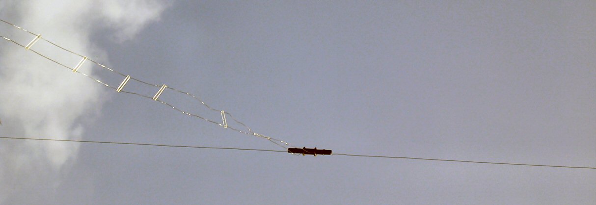 |
|
||||||||||||||||||||||||||||||||||||||||||||||||||||||||||||||||||||||
| Using the antenna for 160m: For this band, both antenna and match don't like each other. Therefore I used the following method: I used the installation as a toploaded antenna. The feeder ends were tied together, and I used my YAESU AT-200 tuner, although I bet that my homebrew tuner will do the trick as well. Using the Central Heating System ground, provides for a good SWR on 160m, and the first contact are promising. In case you are interested, or you miss details that should be clarified, please don't hesitate to email me at my call at qsl.net. Some final words It was a great experience to come to this result. To some this may be all in a day's work, but for me it was a satisfying event. Thank to Carlo (the wire), Steven (for the drilling and installation support) and Charles (performing the first trial tunings in Zandvoort and reminding me of the topload at 160m. Hans Poelgeest, PA0SNY, June 6th 2007 |
And then, after it is all done and fixed, it is good to
enjoy the effect of heat radiation by our Sun: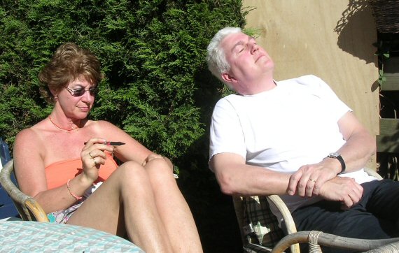 |
Back to the Equipment Page