The
Yaesu FT102 all(hf)band allmode tranceiver.
The FT102 is one of the last transceivers applying tubes.
In the P.A. stage 12BY7 drives 3 parallel 6146’s
The rf-output is 150W to 100W (28MHz).
The receiver is designed for low i.p. with a balanced FET front
end.
The FT102 has very good qualities but also weaker points like the bad
relay contacts.
Caution! the 6146 tubes bias current can run
high caused by secondary emission when the tubes are aging. In worst case even in receive position the PA
bias current runs high!
In my case the
main transformer did overheat and
the fuse blowed out.
This trouble I had
in 2002 during contesting.
The relay contacts can give
troubles special the sub-miniature
Fujitsu relays are a problem they are difficult to replace and or to clean.
Transverter use.
I use the "RF-OUT" RCA jack to connect the transverter.
There is also a separate RX-port available but I preferred to modify the
RF-out port with a small reed-relay so that it becomes a transceive
port for TX and RX.
The RF power level available at the RF-out is about 1mW but if the
limiter R43 560 is reduced to 100ohm the level is 30mW.
CW key-up carrier surpression.
Using this RF-out signal in MODE CW the carrier suppression at
key-up time is only about 20-30 DB.
This is not a serious problem but at local signal levels it gives a
strange sounding CW. The output level at my transverter
is key down 150W and key up still a few m-watts.
It can not be adjusted with the ssb carrier
suppression because this has nothing to do with it.
This problem exists because only 1 stage, the emitter of Q07 in
the RF unit in the circuit is keyed in CW.
In normal operation the CW key-up carrier suppression is better because
then the driver tube 12BY7A bias voltage is also keyed.
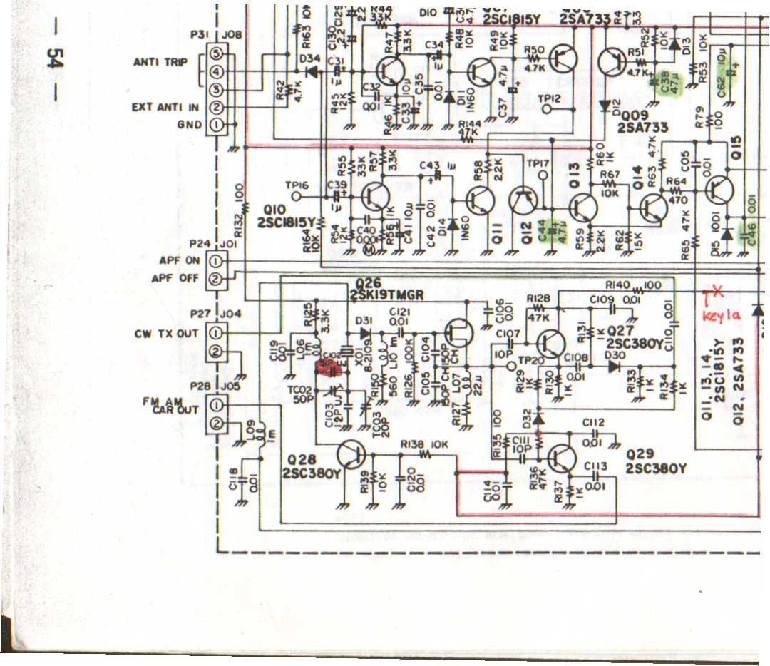
I had to key one extra stage to achieve a better suppression.
Q27 in the AF-unit is most suited for this. It
is supplied with "CW 12V" via R140 100W . This supply must be changed to a keyed 12V.
Unsolder the supply side of R140 from the printed circuit board bend it
up and solder a wire on it.
Lead this wire along the existing cable boom to the collector of Q01 in
the Rect. A-unit.
The base of Q01 is connected to the keyer-input
[Key2] it's collector holds 12V at TX + keydown and that is the level we need.
The "KEY1" signal is also connected to the collector but
through R120 1kW and D13 It is not
usable because the supply current of Q27 would give a few Volts drop.
The difficult part is to connect the collector of Q01. It is not easy to
find the right pad at the back of rect-A unit and
solder the wire there.
But al operations in the FT102 are difficult because it is very packed
inside, its not an empty box you have bought here!
CW KEY CLICKS
At the time I used the FT102 on shortwave I must have had bad CW key
clicks but I can not remember anyone who made complaints about it.
Could it be this key click is smoothed by the normal used P.A. bias keying
as well?
Anyhow with the transverter I had very nasty
key-clicks.
Finally in 1999 I decided to do something about it. And its simple just one tantalium capacitor 2m2 parallel over
R17 in Rect. A-unit does a lot. This C and 22kW R forms an RC network.
The value of C must be at least 1uF the max value depends on how fast
you want to send code.
For high speed MS 1m F is about the
maximum.
Using Electret Microphone type headset
The YAESU original microphone is 600 ohm dynamic.
To connect an
headset with electrets
type elements like PC headsets some minor modification must be done .
The electrets type needs a small dc supply voltage to operate. F.i. the PC
soundcard microphone input supplies 5Vdc for this microphones. (short current is ca 2mA)
Therefore at the FT102 AF-unit
microphone input circuit place a 4k7
resistor between the 8Vdc and the input
of the microphone amplifier. The
existing electrolytic
0.1uF coupling C must be replaced with a ceramic bipolar type.
Now the microphone input carries the needed dc voltage
This is the middle pin 8 of the Japanese microphone connector. The
Phone-patch RCA-input at the backplane is connected with the same line and can
also be used to connect the mike using a cheap standard RCA type
connector.
To use the original Yaesu mike a separator 1uF
tantalium must be placed in the microphone in series
with the element.
This to prevent a bias current flow through the element.