project #2 An
amateur station frequency standard
Why a frequency
standard?
For microwave applications
correct frequency readout is of utmost importance to locate your fellow-ham
operator on your dial.
Next you only have to turn
your antenna and hope for good condx hi.
Available reference
sources
The last decades the well
known off air references such as DCF77 at 77.5 kHz (UKW berichte,
Electron) Deutschlandfunk at 153 kHz (PE1CQQ) and Droitwich at 198 kHz
were often used a base for ham frequency standards.
During the last decade GPS
stuff popped up (currently HP surplus Z3801 seems a good choice), but also
Brook Sheera and Luis Cupido published some interesting material.
I would like to mention the
following links
PE1CQQ frequency standard project
Brook Shera's frequency standard
project
Luis Cupido "ref
lock" project
DK7NT GPS & ZDF controlled
oscillator- part 1
DK7NT GPS & ZDF controlled
oscillator - part 2
The fact that some TV
transmitters use a very accurate picture timing derived from atomic standards
is also very attractive.
Next everyone dreams of
Rubidium standards and the like of course and these too are sometimes found at
the surplus market, though I didn't find one yet.
I have been struggling in
the past with DCF77 locking, but always the 1 second and other phase modulation
was audible after multiplication.
From various sources I have
looked into, phase-locking to ZDF appealed to me.
Pre-requisites
In my case I already had a
reasonable stable oscillator in my shack my 35 year old HP 5245L
counter, containing a 1 MHz oscillator around a glass sealed quartz
plate.
The whole lot is
ovenized for 24 hours per day, leaving the instrument plugged to the mains of
course.
I started off changing the
counter's oscillator circuitry such, that the oscillator is always on too.
I added a 7915 three
terminal regulator and two 47 uF caps from the instruments -35V oven
voltage.
A26(1-6) connector is now
cut from it's original supply and the -15 V from the new regulator output is
rewired to it.
Next I removed the large
tuning capacitor C2 & C3, outside the oven, and I replaced it with the
following circuit.

Figure 1 Modification HP5245L within
oven compartment
Additionally I added a 390
ohm series resistor and 10 nF series capacitor from emitter of A26Q4 to a (new)
BNC receptacle at the instrument's rear using miniature coaxial lead via a free
pin on PWB A26.
Another (new) BNC
receptacle was added to carry the tuning voltage, also via a coaxial lead.
Note that from now on
always an external stable 5V bias is necessary to allow proper instrument
operation
The tuning sensitivity need
not be large. I experimented somewhat by listening to the oscillators 144th
harmonic on my TS700, while counting the beat-note frequency with the
counter itself, which is allowe since detuning is very small and precise
absolute values are not necessary.
The idea was to have a
stable DC voltage such as a Analog Devices REF02 band-gap reference to switch
to whenever no timing reference is available.
I found about 100 Hz of
shift at 144 MHz for 1 Volt tuning voltage deviation. This means about 2/3 Hz
at 1 MHz.
TV horizontal sync
signal as reference
The horizontal or line sync
frequency of European TV is 15625 Hz which is exactly 64 μsec.
The timing signals can be
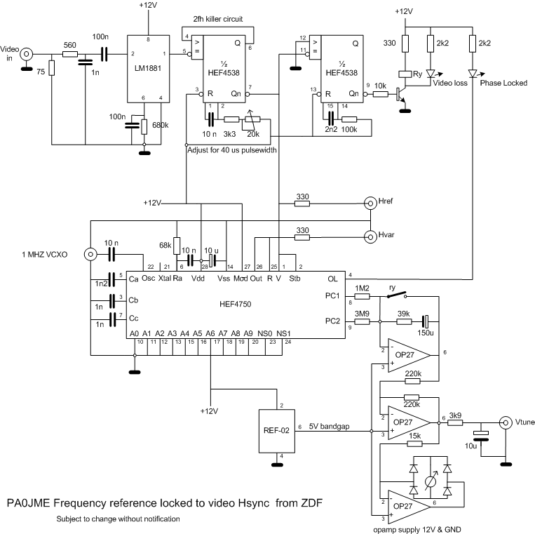
separated from the video-signal using a LM1881 sync-stripper.
The negative edge of the
sync within the video signal is the reference edge.
Special about Zweites
Deutsches Fernsehen (ZDF) is that their timing is governed by the atomic
standard at Frankfurt DCF77.
A slight problem are the
serration pulses during flyback which differ slightly to discriminate between
odd and even fields during transmission of a single TV-frame (picture).
Within these fly-back
periods, the line frequency actually gets doubled, but the negative edges of
the sync signal stay aligned, though at double frequency.
This double frequency can
be gated out using a one-shot circuit which is tuned to be slightly larger (40
μsec) than the double line-frequency period (32 μsec).
This disables the second
edge due to the double frequency and permits perfect timing without phase-jumps
into the PLL due to odd/even field serration pulses.

Figure 2 PAL sync timing around
'fly-back'
Jitter
There is an appreciable
amount of jitter on the Hsync if one measures the edges at some distance away
from the trigger edge. I still have to determine the frequency content of this
jitter.
If the PLL bandwidth is narrow enough this shouldn't be a problem.
The PLL circuit

I had some nice
phase-detector HEF4750 chips lying around which could do a perfect job to
my mind. Actually it is a frequency and a phase detector in one.
The frequency discriminator
allows for coarse control, while the phase-detector is for the precise action.
The phase-detector is a so
called dual sample and hold circuit which once was patented for its low
spurious feed-through
It's operation is rather
simple but to my mind not always understood by various hams.
The basic idea is that a
constant current source charges a capacitor started off by zeroing the charge
by the reference signal's edge.
If the feedback signal's
edge 'comes along' within the capacitor charging period, charging is
stopped and the instantaneous voltage of the capacitor is stored in the next
capacitor.
If the feedback edge is
outside the window created by the the maximum charging period the control
action is 'handed over' to the frequency discriminator.
If the feedback frequency
is too low, the discriminator indicates UP, when too high it indicates DOWN.
Within the charge period it is off (high-Z)
This charging-period limits
the reference frequency somewhat, typically around 10 kHz. The smaller the charging
period is with respect to the reference period, the higher the phase-detector
gain will be.
Since my oscillator is at
1MHz this must be divided by 64 to obtain 15625 Hz, so further reducing my
oscillator gain to about 40 milli-radians/V.
The phase-detector extra
gain potential is welcomed. I measured the gain of the phase-detector to
be 700 mV over 2.45 milli-radians = 285 using a 15 volt
supply, timing cap of 220 pF and a current source set resistor of 68 kohm. The
Phase-frequency detector part has a fixed gain of Vdd/(4π)
The frequency discriminator
and phase control voltage are fed through the PI loop-filter to the Xtal
oscillator.
The integrator is shorted
out if video input fails. so feeding the band-gap voltage into the loop
assuring a kind of holdover at lower accuracy
If one observes the control
voltage with an oscilloscope one sees voltage fluctuate with picture content.
During fly-back no voltage change occurs ,so no influence of either teletext
nor VITS.
This means some frequency
wander remains due to some imperfection in the sync-stripper which introduces
some slight period variation.
Being quiet around fly-back
indicates that 50 Hz (field-frequency) FM sidebands will be present in
the output signal
This can be removed by
sampling the control-voltage once lock is declared by field derived pulses. I
didn't experiment with that yet.
Fluctuation is about 100 mV
peak to peak, i.e. some 66 milli-Hertz peak peak on 1 MHz, 66 x 10-9
The effect shows observing
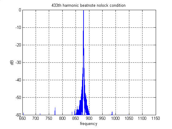
the 433th harmonic of the 1MHz reference in my IC402 SSB transceiver while
feeding about 30 seconds of audio beat-note in to my PC soundcard
FFT-ing the audio is much
revealing. Very noticeable are the 50 Hz sidebands, which is the TV
transmission field-frequency
Field-frequency
re-sampling or low bandwidth PLL is certainly going to help suppressing the 50
Hz pitch FM sidebands.
Note that the unlocked tone
is slightly lower in frequency, actually that's the drift of my IC402 which was
just switched on for the purpose.
Later I verified that audio
changed much less, observing about 1 Hz which is an obvious error using 1
second gating the frequency counter.
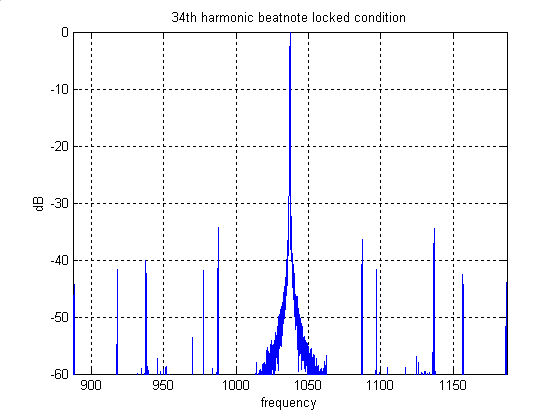
The narrow span shows that
performance of the PLL has room for further improvement with regard to
close-in noise, still I am very satisfied for the moment.
Since this is 433th
harmonic, sidebands of the 1 MHz signal will be at least more than 50 dB down
from the values shown here, theoretically that is.
This already shows by observing the 34th harmonic, though 50 Hz sidebands remain clearly visible.


The meter circuit on the
tuning voltage shows this spread on the average tuning voltage.
The TV receiver

From an acquaintance
I obtained a surplus Philips' tuner module UV916H which has a
synthesizer controllable via I2C.
So for setting the
synthesizer I had to do some programming. I preferred C and found a
piclite C compiler http://www.htsoft.com/products/piclite/piclite.html
on the internet.
I added an I2C.
ADC/DAC, to allow metering and AGC and some other measurements outside this
project's scope
My C source i2croutines
(and a not used dac_routine)
can be found here too.
The receiver is further
without comment, since it is relatively straight forward.
If the input signal is too
low, the micro-controller pulls the video into the off condition.
Additionally I built
another PLL using a 10 MHz TXCO obtained from the
This frequency is locked to
15625 Hz divided down from my 1 MHz standard. This too is a rather narrow
bandwidth PLL.
Furthermore I added another
PLL at 100 MHz locked to the 10 MHz one. This one uses a Minicircuits
VCO, hence this PLL has a much wider bandwidth.
It's reference is the 10
MHz TCXO and the phase-detector used is a derivative from the well known 4046,
the redesigned 74HC9046
In this way I can mix down
my microwave LO's running around 90 MHz .. 100 MHz to more manageable
frequencies.
I didn't throw away my old
DCF77 receiver. I use it's pulsing carrier o/p to feed to another PLL to
remove amplitude changes.
Another PLL locked to the 1
MHz one generates a 77.5 kHz signal which can be open loop compared to the
received carrier.
Using a dual beam oscilloscope
one can observe the stability of the 1 MHz source w.r.t. the received DCF
carrier.
I already did some
measurements and they support my satisfaction up to now.