HP8709A use with HP8690 by Rien Eradus PA0JME, [email protected]
An old
acquaintance, Bert Bruntink living in DL for some decades, obtained a HP8709A
which he wants to use to phase-lock his HP8690 sweepers. This lead to some thoughts on this subject, hence this story.
The HP8709A
is a synchronizer for the HP8690 series of sweepers.
The HP8690
series sweepers can accept plug-in units with a BWO as the basic oscillator.
The helix
voltage of these BWOs is rather high voltage and is
swept by the mainframe using HV tubes in it’s output stage.
The helix voltage can be up to 2200V.
The helix
voltage is shaped with a diode-resistor network within each individual plug-in,
and fed back in to the sweeper mainframe to have a linear voltage to frequency
relation.
Some time
ago I made an external input for the HP8690 to enable external sweeping with a
low-voltage from -4 to +4 Volt from my PC DAC.
The divided
down helix voltage is normally output to the mainframe’s front via BNC labeled
with “SWEEP OUT”.
The low to
high-voltage is done by shunting the manual sweep pot-meter with a
HV-transistor current source, such that the voltage across this pot-meter
changes from about 0 to 280 V.
The circuit
is checked using a HP8690B with a 8696A plug-in (18-26.5 GHz)
It showed
that not the entire range from 0 to 280 V is effectively used a sweep voltage.

The input
voltage of -4.096 V equals a DAC value of -2048 and 4.096V equals a DAC value
of 2048 and the figure shows an approximate linear behaviour
from -1700 to 1300, i.e. (1700+1300)*8.192/4096 = 6V span. The effective EMK
voltage is from -3.4 up to 2.6 V
Using the
18 to 265 GHz plug-in, the input sensitivity is (26.5-18)/6=-1.3 GHz/V
The minus
sign is due to the negative slope of the sweep-voltage output w.r.t. the input voltage.
HP8709 interfacing
Referring
to the HP8709A manual, there are two outputs of the phase-detector. The 1st
one, labeled HELIX OUTPUT, has an output impedance of 200 Ω and -12 up to
+12 V output-swing. The 2nd one labeled
SERVO OUTPUT has and impedance of 70 kΩ, with
-.8 up to .8 V output-swing. Obviously the SERVO O/P is .8/12 x HELIX = 2/30.
The
HP8709A’s modulation sensitivity has 3 positions which refer to the HELIX
output
|
Position |
Modulation sensitivity HELIX o/p |
Modulation sensitivity SERVO o/p |
|
1-4 GHz |
0.5 to 1
MHz/V |
7.5 to 15
MHz/V |
|
4-12.4
GHz |
1 to 2.5
MHz/V |
15 to
37.5 MHz/V |
|
12.4-40
GHz |
2.5 to
6.0 MHz/V |
37.5 to
90 MHz/V |
First,
neglecting phase, the servo output and tune-voltage need to be added in proper
proportion to each other. The mean output in the higher range is √37.5 x
90 = 58 MHz/V or 17 mV/MHz and the tuning slope is
1300 MHz/V, i.e. 770 µV/MHz. This boils down to an additional attenuation of
1/22 of the servo voltage.

Figuur 1 suggestion for a circuit to add phase detector voltage to a locally generated tune-voltage
The circuit operates as follows. The detector voltage is buffered by a voltage follower built around A2. The 8709 SERVO output is fed into “in”. The 10 turn pot-meter creates the tuning voltage and the ratio of R9 and R10 determine the approximate required 1/22 attenuation. If the circuit is to feed the proposed low to high voltage converter, a nominal output on A4 should be between -4.096 to 4.096V for the highest and lowest frequency respectively. The phase inversion of A4 together with the phase inversion of the low to high voltage converter cancel as far as control theory is concerned.
A1 and A2 are voltage followers to adjust the required top and bottom voltage for the tune pot-meter. The output voltage of A1 is positive and has to translate to -3.4 V on A4.
The gain of A4 is -1 for the tune-voltage, so A1 shall be adjusted for +3.4 V using R7.
Evidently A3 output shall be adjusted for -2.6 V using R3.
R12 feeds the low to high-voltage converter.
Low
to high-voltage converter
Back in the late eighties
or early nineties I built a PC ISA card published by the Dutch Elektuur magazine in May 1988 to control my swept
measurements. This is an eight channel 13 bit ICL7109 ADC and a single channel
PM7548 12 bit DA output with an output resistance of 10 kΩ
and an open voltage from -4.096 to 4.096 Volt
The ADC is pretty slow
though, about 120 ms, so you should not be in a hurry. The board also hosts a 8255
parallel IO and a 8253 counter, but I never used the latter one.The
sweep-speed of the circuit below operates OK at least up to 1 kHz. At 10 kHz
the op-amps appear to be too slow. You can parallel the input of the circuit
with the J1 BNC connector on the instrument’s front. The trigger circuit is AC
coupled and of no need if PC sweeping. The circuit at the right is the manual
sweep pot-meter, which is paralleled with the transistor
I built my circuit on a piece
of experimenting board as a piggyback on power-supply card A14, the input is
routed to free pin 8 on the board, a shield wire is routed from connector
A2-pin 44 and shield to A2-43, those are connected to the input trigger BNC.
Another separate shielded wire is routed from pin 12 of A2 to the collector of
the BF859. Don’t use any of the other presumed free pin’s of A14, since they
are not free on the mother-board !!!Note that you
cannot use the manual sweep anymore unless the input is negative biased such
that the transistor is in cut-off i.e. the new sweep-input should be held below
-2 Volt.At open input the emitter pot should be
tweaked for 2mA collector current. The gain of the first amplifier is 0.5 x
since the input resistance is 20 kΩ, i.e the sum of the
PC-card output’s resistance and this amplifier input resistance, while the
feedback is 10 kΩ.The
lower op-amp creates a -2V bias from the -6.3 and 20 Volt supply, to enable a
suitable sink for the current source formed by the right-hand upper op-amp, the
transistor and it’s emitter resistor. At 4 Volt from the PC card the output of
the 1st op-amp will be 2Volt so forcing 4 Volt/1 kΩ =
4mA current. This result in about zero volts at the top of R1 pot-meter,
which under all circumstances should have it’s wiper
contact in the “top position”, i.e. at A2-R5’s end. At -4 Volt
from the PC-card the transistor will be cut-off and the voltage at junction R5
and R1 will be max. The result is measured in the figure below. The assumption
that the complete range of the manual pot-meter is used proved to be wrong, part of the range is saturated. This can be altered by changing some
of the resistors in the circuit, i.e. offset and gain.

Figuur 2
Possibility
of using the HP8690 EXT FM input
The HP8690 has a BNC labelled EXT FM which was considered to be used as a phase detector input too. Since the -3dB bandwidth of this input is however just a few kHz, I expect it to be too low to obtain a stable control. You can experiment with it though, but the 8709’s SERVO O/P should be used and the voltage should be additionally attenuated by 550/58 = +/- 10x using a HP8696A 18.0 to 26.5 GHz plug in. The input impedance of the EXT FM input is 100 kΩ.
The table shows some suggested attenuation values for different types. An advantage is that just simple hardware is required and there’s no need to open the HP8690.
|
TYPE |
Ko on EXT FM MHz/V |
RANGE GHz |
SERVO O/P MHz/V |
Attenuation |
|
HP8691A/B |
63 |
1.0-2.0 |
7-15 ≈ 10 |
63/10 ≈ 6 |
|
HP8692A/B |
126 |
2.0-4.0 |
7-15 ≈ 10 |
126/10 ≈ 13 |
|
HP8693A/B |
252 |
4.0-8.0 |
15-37.5 ≈ 24 |
252/24 ≈ 10 |
|
HP8694A/B |
277 |
8.0-12.4 |
15-37.5 ≈ 24 |
277/24 ≈ 12 |
|
HP8695A/B |
352 |
12.4-18.0 |
37.5 – 90 ≈ 58 |
352/58 ≈ 6 |
|
HP8696A/B |
550 |
18.0-26.5 |
37.5 – 90 ≈ 58 |
550/58 ≈ 10 |
|
HP8697A/B |
850 |
26.5-40.0 |
37.5 – 90 ≈ 58 |
850/58 ≈ 15 |
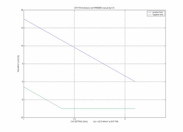
Figuur 3 HP8691
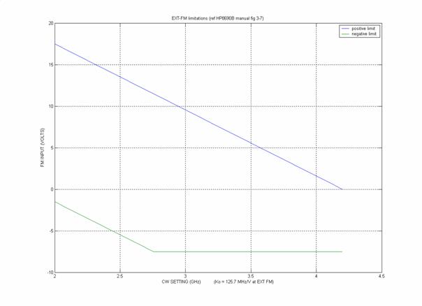
Figuur 4 HP8692
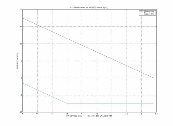
Figuur 5 HP8693
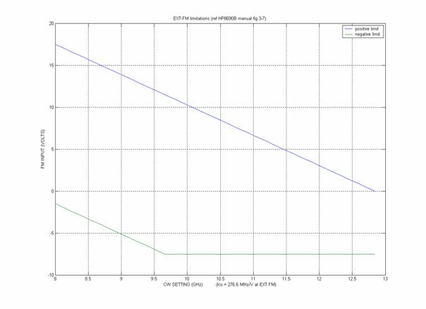
Figuur 6 HP8694

Figuur 7 HP8695
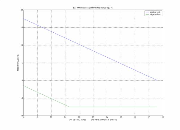
Figuur 8 HP8696
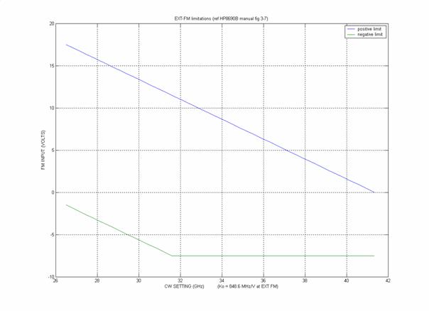
Figuur 9 HP8697
Summary
of plug-ins
1.0000 1.2000 1.4000 1.6000 1.8000 2.0000 2.1000 HP8691A/B
2.0000 2.4000 2.8000 3.2000 3.6000 4.0000 4.2000 HP8692A/B
4.0000 4.8000 5.6000 6.4000 7.2000 8.0000 8.4000 HP8693A/B
8.0000 8.8800 9.7600 10.6400 11.5200 12.4000 12.8400 HP8694A/B
12.4000 13.5200 14.6400 15.7600 16.8800 18.0000 18.5600 HP8695A/B
18.0000 20.2000 21.4000 23.1000 24.8000 26.5000 27.6000 HP8696A/B
26.5000 29.2000 31.9000 34.6000 37.3000 40.0000 41.3500 HP8697A/B