Project #3 Sweeping the
HP8690B with your PC
Back in the late eighties
or early nineties I built a PC ISA card published by the Dutch Elektuur magazine in May 1988 to control my swept
measurements.
This is an eight channel 13
bit ICL7109 ADC and a single channel PM7548 12 bit DA output with an output
resistance of 10 kΩ and an open voltage from
-4.096 to 4.096 Volt
The ADC is pretty slow
though, about 120 ms, so you should not be in a hurry. The board also hosts a 8255 parallel IO and a 8253 counter, but I never used the
latter one.
The sweep-speed of the
circuit below operates OK at least up to 1 kHz. At 10 kHz the op-amps appear to
be too slow.
You can parallel the input
of the circuit with the J1 BNC connector on the instrument’s front.
The trigger circuit is AC
coupled and of no need if PC sweeping.
The circuit at the right is
the manual sweep pot-meter, which is paralleled with the transistor
I built my circuit on a
piece of experimenting board as a piggyback on powersupply
card A14, the input is routed to free pin 8 on the board, a shield wire is
routed from connector A2-pin 44 and shield to A2-43, those are connected to the
input trigger BNC. Another separate shielded wire is routed from pin 12 of A2
to the collector of the BF859. Don’t use any of the other presumed free pin’s
of A14, since they are not free on the motherboard !!!
Note that you cannot use
the manual sweep anymore unless the input is negative biased such that the
transistor is in cut-off i.e. the new sweep-input should be held below -2 Volt.
At open input the emitter
pot should be tweaked for 2mA collector current.
The gain of the first
amplifier is 0.5 x since the input resistance is 20 kΩ, i.e the sum of the
PC-card output’s resistance and this amplifier input resistance, while the
feedback is 10 kΩ.
The lower op-amp creates a
-2V bias from the -6.3 and 20 Volt supply, to enable a
suitable sink for the current source
formed by the right-hand upper op-amp, the
transistor and it’s emitter resistor.
At 4 Volt from the PC card
the output of the 1st op-amp will be 2Volt so forcing 4 Volt/1 kΩ =
4mA current.
This result in about zero
volts at the top of R1 pot-meter, which under all circumstances should have it’s wiper contact in the “top position”, i.e. at A2-R5’s
end.
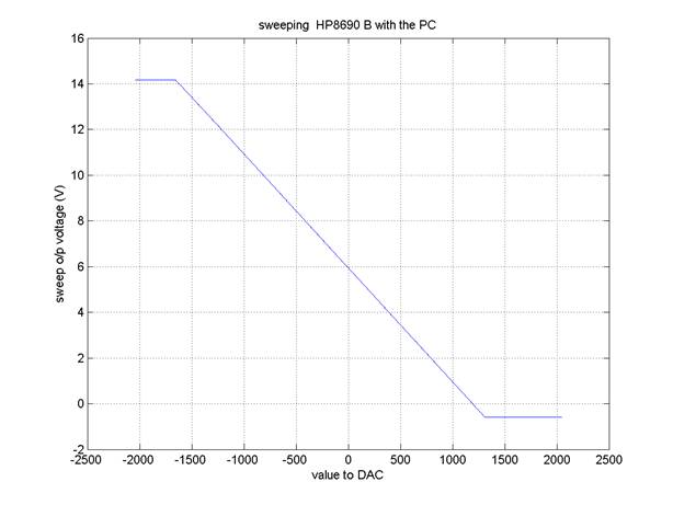
At -4 Volt
from the PC-card the transistor will be cut-off and the voltage at junction R5
and R1 will be max. The result is measured in the figure below. The assumption
that the complete range of the manual potmeter is used proves to be
wrong, part of the range is saturated. This can be altered by changing some of
the resistors in the circuit, i.e. offset and gain.
Once modified and tested the
circuit diagram will be adapted.