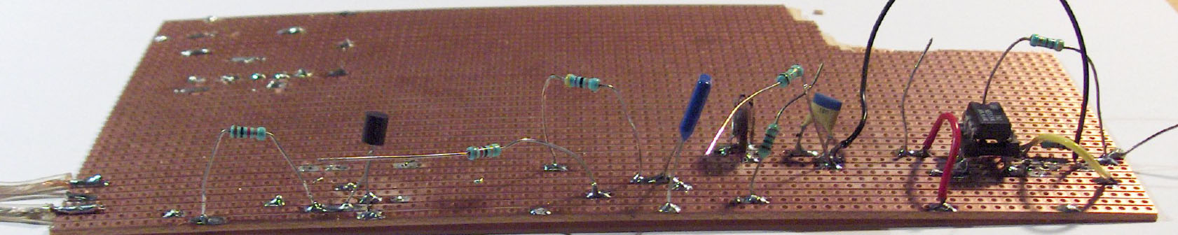
 So I went on to the receiver, which is basicly a coil and a capacitor tank tuned to the transmitter frequency (40 kHz).
 The next thing I am going to make is some ultra-sonic obstacle detector.
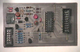 The David Tait "TOPIC" Pic
programmer
The David Tait "TOPIC" Pic
programmer
I use it for my PIC16C84 projects. It was fairly easy to build and works
flawlessly on my old 386 PC. On my newer Pentium machines it does
not work though. This is because the parallel port is not of the
old totelpole type. On most PC's this can be altered from the
boot-setup program, but I find it's easier to use the old
faithfull 386 instead.
I have made one modification to the circuit though: I have added a 10pin header
which I use for in-circuit programming. I only need to have a
similar 10pin header on each PCB I make and voila! a
flatbandcable connects the programmer to the circuit under
development. More on that later.
Visit David Taits home page
. A GREAT source of PIC links.
 A versatile psu using the LM317T regulator
This is a easy to build power supply. It uses the LM317T regulator,
which enables the output voltage to be preset from 1,25 - 30V, and to deliver up to 2A.
I have used this circuit in a number of projects where the 78xx/79xx series is not adequate
or the possibility of changing the output voltage is necessary.
The output voltage is changed with the trimmer R1 (which of cause can be substituted with a
potentiometer if You wish). As you can see from the diagram the trimmer is in parallel
with a fixed resistor R2. I have made space for R2 so that I can use whatever trimmer
I have in my junk-boxes (se excel calculations for more).
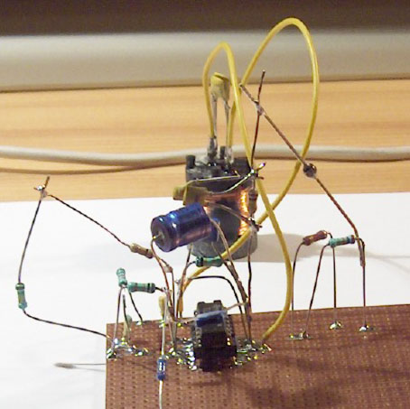
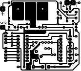
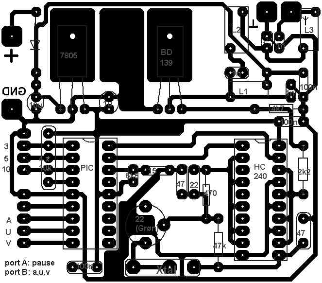
The local Jamboree group wanted a new set of FOX-hunt transmitters.
Therefore this project was initiated. It incorporates a xtal controlled 160m
transmitter (1.825 Mhz).
The transmitter is excited by a PIC16C84 which contains a program for transmitting
in morse the call OZ7FOX/A, OZ7FOX/U or OZ7FOX/V (selected by a switch).
The speed of the morsecode is selected by a switch as well.
The pausetime between transmissions is selectable to 1, 3 or 6 seconds by a switch.
The transmitter is a slightly modified 74hc241 80m transmitter (from the ARRL handbook),
with a BD179 as PA, and a 3-pole low pass filter. All thanks to OZ1KTC, Per.
ASM source (comments are mostly in Danish)