
Everyday VHF, UHF, and SHF propagation
700 km DX anytime using troposcatter
Palle Preben-Hansen, OZ1RH
If you are you an experienced DX'er you know that most stations work stations 5-800 km away in the VHF/UHF contests regardless of band conditions. How come you can make a 700 km QSO on a dead band?
Are you a FM-freak and gossip through your local repeater? Then you may want to have a range of 3-400 km on 2 meter or 70 cm with simple equipment.
With 10 W SSB on 144 MHz and a 10 dB horizontal antenna the range on troposcatter is over 300 km, much better than a repeater. 100 W SSB and a 15 dB antenna in the clear you make 500+ km anytime. Troposcatter works from 50 MHz to over 10 GHz.
Troposcatter is responsible for most daily QSO's and contest QSO's, but perhaps also the least known propagation. In this lecture troposcatter is examined inside and out, in order for you to learn how to make best use of a propagation, which is always there.
Contents:
Preface
*Tropospheric propagation terminology
*4/3 earth radius = radio optical view to DX?
*Troposcatter - daily DX!
*Path loss, expected range of your station.
*Scatter angle and path loss
*Radiation angle, ground reflection and ground gain
*Flat Ground
*Sloping ground
*Selection of a super QTH
*Is troposcatter dependent on frequency?
*Polarization
*Signal quality
*Fading, diversity reception
*Height of troposphere
*No. of scatters => antenna gain loss
*Airplane reflection or troposcatter
*Greater range on 70 cm than on 2 m
*Conclusion
*Literature
*
Target group:
Those who think VHF and UHF can only be used to chat via the local repeater, and the experienced DX-freaks, who would like to know why they can work so many stations so far away and what it takes to improve the range.
Objectives:
After the lesson the participants should:
- know about troposcatter propagation
- have a general idea on what equipment is needed
- know why the range is limited to app. 800 km
This lecture was given at the Weinheim UKW-Tagung 1994, but I have now updated and enhanced it with new knowledge and experience from the past 5 years. It will be held in English, but questions may also be asked in German and French (QRS s.v.p.).
Lecture by OZ1RH, operator at OZ5W/OZ9EDR contest team.
© OZ1RH
My call is not heard often on the bands. I was licensed in 1963 and qualified half a year before being 18 for my extra class license. I worked mostly HF and hold DXCC. I have done some 144 MHz contesting since the late sixties and in the beginning of the nineties I started being active on VHF from OZ9EDR/OZ5W. I wondered which propagation made us work 700 km in every contest. I read some books, and found troposcatter does the trick. Now I want to share this knowledge with you.
I have no education in electronics, but hold bachelor degrees from the Copenhagen Business School of Commerce in public administration and organization, strategy and planning. I am employed in the computer business, so this text is based only on my leisure time study of the referenced literature and on my experience from the bands. I know my words are not the whole truth, but I hope they come closer to "nothing but the truth".
Much of the literature I have read on scatter dates back to 1954-60, where it was a hot item among scientists and radio engineers. I trust we may still use this old information, as the characteristics of the propagation itself have not changed in the past 40 years.
Troposcatter was used by commercial services and the military 1950-93, so information on troposcatter was to some extend restricted in those days due to security reasons. Some of the sources I have read mention "Printed with permission of the Admiralty" or "Some essential parts are deleted due to US government policies". Thus troposcatter so far has been quite unknown to many amateurs.
Today troposcatter is little used commercial, as satellite communication is available. Troposcatter is however still used over the North Sea for communication with the oil platforms. Paying no attention to the lack of commercial use, radio amateurs working on an otherwise dead VHF/UHF/SHF band do take advantage of troposcatter communication most often during contests.
To make my lectures more lively I do them without a fully written text and I base my speech only on my prepared PowerPoint slides with overheads as backup in case of PC panic. If you ask some interesting questions I will be happy to answer, and this will make the lecture even more interesting for you. My lecture may thus include other ideas than presented here, and you can't be sure it will include all of the following. So my best advise to you is to read the text and come to the lecture with some good questions.
Tropospheric propagation terminology
Many amateurs talk about ‘tropo propagation’. The word 'Tropo' is not in any of the books or research articles on propagation I have read. It seems amateurs uses the word ‘Tropo’ for various propagation modes taking place in the troposphere because they do not know better. The word 'Tropo' should never be used alone. The relevant propagation modes in the troposphere are:
Line of sight (0-30 km, depending on height) is always available. The antennas see each other and have more or less clearance of 1. Fresnel zone. Generally S9 signals with QRP.
Diffraction (30-100 km?). Waves follow the curved earth a little, thus extending line of sight somewhat. Knife edge diffraction in mountain areas is a better known but special case of diffraction.
Refraction. (30-100 km?). Waves bent towards the earth due to the fact that the atmosphere gets thinner at higher altitude. Actually humidity plays a greater role than atmospheric temperature and pressure. Diffraction and refraction combined extends line of sight range, but signals will have QSB.
Inversion (200+ km ?). Temperature/humidity can sometimes suddenly increase at higher heights, 100-1.000 m up and our radio waves are reflected back to earth.
Ducting (1.000+ km, e.g. Hawaii to California at 4000 km). Radio waves are sometimes trapped like in a wave guide between an inversion layer and the ground or between two inversion layers. Little attenuation, thus good signal strengths. Often signals are only heard at each end of the wave guide, and conditions are only good between relatively small geographical areas.
Troposcatter (100-700+ km). Scattering in the troposphere in the common volume of the radiation from the beams. This is what will be discussed in details in the following.
All the above mentioned propagation modes are of tropospheric origin, where the cause of propagation is some kind of change in the refractive index of the atmosphere - that is change in temperature, density and humidity.
Troposcatter is to some extend influenced by the climate. The following is only dealing with a temperate climate like in northern or central Europe. If you are in an equatorial, sub-tropical, desert, Mediterranean or polar climate zone please read the texts from CCIR Study Groups, ITU, referenced at the end.
4/3 earth radius = radio optical view to DX?
As long as you have line of sight to your QSO partner you have good signal strength even from a FM walkie. Depending on how good your QTH and how high your tower is you could have line of sight up to 30-50 km.
Diffraction and refraction extends your range beyond line of sight, but signals will have QSB in this diffraction zone. This means that the radio horizon is further away than the optical horizon, and this diffraction and refraction effect is often modeled by assuming the earth is flatter than it really is, that is it is a sphere with 4/3 radius of the real earth.
Using the formula d1(km)=4,1(Ö h1 + Ö h2) where h is the antenna height in meters, you can calculate your the radio horizon. If h1=2 and h2=100 m you get a range of 50 km. If you climb the alps so h1=2 and h2=4.000 m you get 300 km, not much DX even from a super high mountain peak.
In the old days the radio horizon was considered the max distance possible on UHF/SHF. Still many books mentions UHF/SHF as only line of sight communication and many hams only active on FM believe this. Once you have tried SSB you will have realized that a 3-500 km QSO can be made anytime. Clearly some other propagation mechanism than line of sight is responsible for your daily DX QSO's. This is troposcatter.
Troposcatter is spreading of radio waves in the troposphere caused by irregularities in the atmosphere. The troposphere is the atmosphere below an upper limit called the tropopause, which is in a height of app. 10 km. Above the tropopause the temperature is constant, there is little humidity and no movements in the air, thus few irregularities to scatter our radio signals.
Troposcatter is always present and as we see later independent of frequency from below 144 MHz to 10 GHz.
Troposcatter was used by commercial services and the military 1950-80, so information on troposcatter may have been restricted in those days due to security reasons. Also the required SSB/CW power and beams were not so common among amateurs in those days as today. Thus troposcatter so far remains quite unknown to many amateurs.
To make it worse, the textbooks on troposcatter are written for the commercial world, who has other interests than amateurs.
|
Important factors regarding troposcatter: |
||
|
Commercial interest |
Amateur interest |
|
|
Range |
2-400 km |
4-800 km for real DX. |
|
Reliability |
Over 99,9% wanted |
Less than 50% OK for a marginal QSO. |
|
Fading |
Reduces bandwidth or bitflow |
Only fast fading >50 Hz may degrade intelligence. Slow fading may give QSO in up periods. |
|
Bandwidth |
Large, 15-60 phone channels |
Small, SSB= 2 kHz, CW=100 Hz |
|
Location |
Chose "the best QTH" and pay for it... |
Home is home, choosing a good QTH is only possible for /P operation. |
|
Enhanced propagating conditions |
Unwanted, means interference problems |
Wanted, means more QSO's |
Thus the textbooks on how to design troposcatter links describes many factors not too relevant for amateur DX. Today newer text often considers troposcatter as just another source of interference to microwave links.
Path loss, expected range of your station.
Path loss can be calculated to within 1 or 2 dB using the formulas in the textbooks. Lets skip the mathematics and look at the following diagrams. They tell us what to expect from troposcatter on 144 and 432 MHz:
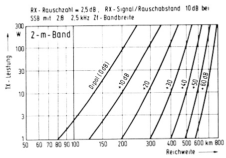
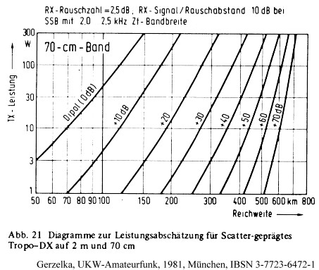
The diagrams were done in 1981 and are conservative, as we today quite easy can have a noise figure better then 2.5 dB in our RX. However the man made noise in cities will most likely be the limiting factor at least on 144 MHz.
The antenna gain shown in the diagrams are the combined gain of the two stations. Suppose you and your QSO-partner only have a small beam with 10 dB gain on 144 MHz the 20 dB curve tells you to expect a range of about 290 km with just 10 watts SSB. On 432 MHz a beam with the same boom length (perhaps 3 meters) will have app. 15 dB gain. Your range on 432 MHz is then seen on the 30 dB curve and is about 270 km. The interesting thing here is that the range is about the same on 432 MHz as on 144 MHz.
Two better equipped stations with a 15 dB antennas and 100 watts will have a range of 500 km on 144 MHz.
Path loss increases app. 10 dB per 100 km for each of the first few 100 km. At longer range the path loss increases with less than 10 dB per 100 km. At temperate climate the 50% path loss for land paths at 1 GHz:

|
Range |
Path loss increases |
|
3-400 km |
+11 dB |
|
4-500 km |
+10 dB |
|
5-600 km |
+9 dB |
|
6-700 km |
+7 dB |
|
7-800 km |
+6 dB |
|
8-900 km |
+5 dB |
|
9-1.000 km |
+4 dB |
CCIR, Annex V, fig 21
Troposcatter range of equipment capable of moonbounce operation taken from Radio Communications, August 1981:
|
MHz |
EME path loss dB |
Tropo range km |
Equipment for EME (in 1981) |
Antenna Gain |
|
144 |
252 |
990 |
500 W, 3 dB NF, 100 Hz, 4 x 16 elm |
21 dBi |
|
432 |
262 |
940 |
500 W, 3 dB NF, 100 Hz, 20 ft dish |
26 dBi |
|
1296 |
271 |
890 |
500 W, 3 dB NF, 100 Hz, 16 ft dish |
34 dBi |
|
2304 |
276 |
860 |
100 W, 3 dB NF, 100 Hz, 16 ft dish |
40 dBi |
|
10368 |
289 |
790 |
50 W, 3 dB NF, 1 kHz, 12 ft dish |
50 dBi |
The past 20 years has provided us with low noise transistors, so a noise figure of 1 dB is standard up to at least 10 GHz. The lower noise figure can be utilized better on the higher bands where the noise level is lower. The conclusion is that if you are capable of EME, your troposcatter range is around 900 km on all bands 144 MHz to 10 GHz.
I do not know if there is any limit to troposcatter range as long as power and antenna gain is improved. Some of the curves in the literature on troposcatter path loss go to 1.200 km. In the sixties there were two 400 MHz troposcatter link from Thule, Greenland to Cape Dyer and Baffin Island, a distance of 590 and 625 statute miles, about 1.000 km. On a military budget is was possible to setup 40 m dishes and to run 10-100 kW. For us amateurs we all too soon hit the license limit and/or the limit of our credit card. For most of us this limits our range to around 800 km on troposcatter.
The better equipped eme stations could investigate the maximum range of troposcatter by using modern signal detection techniques like FFTDSP. The most difficult task is likely to have the needed low angle of radiation. Few eme stations have their antenna on a 30-40 m tower or reside on a hilltop, either of which is needed to get really low angle of radiation. Never the less I predict 1.000-1.200 km troposcatter QSO’s can be done by the top eme stations anytime with the present day DSP techniques. I would like to hear about results in this direction – you should once in a while try to do something ‘impossible’ to get experience.
The scatter angle should be as small as possible as each degree of scatter angle cost 9-12 dB in signal strength. The scatter angle is directly proportional to the radiation angle used at each station, and increases with increasing angular distance between the stations.
IRE Transactions on Communications Systems, September 1960
A troposcatter QSO is comprised of 3 legs:
The angular distances must be calculated taking refraction into account, that is the effect of the diminishing refractivity of the atmosphere with increasing height causing the radio wave to be bent (refracted) towards the earth. This refraction is also known as 4/3 R, meaning that to radio waves the earth looks flatter, as if its radius were 4/3 of its actual radius.
As you know from satellite communications the free space loss is relatively small, so you want to have as long d1 and d2 as possible. That is one of the reasons we climb whatever mountains we may find to do /P operations.
Using the formula d1(km)=4,1(Ö h1) where h is the antenna height in meters over the horizon, you can calculate the distance to the radio horizon taking refraction into account. This formula gives you:
|
h1/h2 in meters |
d1 in km |
|
10 |
13 |
|
50 |
29 |
|
100 |
41 |
|
200 |
58 |
|
500 |
92 |
|
h1/h2 in meters |
d1 in km |
|
1.000 |
130 |
|
2.000 |
183 |
|
3.000 |
225 |
|
4.000 |
259 |
As you can see the distance to the radio horizon is small compared with the wanted 700 km DX even from high mountains. Typically a 700 km troposcatter QSO is done with two legs of line of sight less than 50 km and one scatter leg of 600 km. One conclusion of this is that mountain climbing is not real necessary to work troposcatter DX. As the highest mountains in Denmark are hills of less than 200 m there are still hope for us OZ-contest teams. And the PA0’s may go ahead and work DX from sea level. The theory back up the fact that lowlanders can do well in contests.
As the distance between the stations increase the scattering takes place higher and higher in the troposphere. For the longer DX QSO’s the lowest part of the scattering volume is several km up. One effect of this is that a high mountain at the midpoint between the two stations has no influence on the signal. Thus troposcatter can span the Alps with no problems as long as both stations has a clear horizontal view to the horizon. So daily transalpine QSO’s are no wonder, just troposcatter QSO’s.
As troposcatter loss increases with the scatter angle you will obviously want to have as small scatter angle as possible. This means that the two radiation angles should be kept as small as ever possible since every degree cost 9-12 dB. If there is a mountain in the direction of the other station you must have a high radiation angle to shoot over the mountain, and this will cost you many dB in signal strength. Even though knife edge diffraction may bring your signal around the mountain, the extra 30-50 dB diffraction loss will prevent you from real DX. You should look for a QTH with a clear view to the horizon at sea level. You may even have a small negative viewing angle to the horizon from a high cliff overlooking the sea.
Let’s say you have found such a super QTH. The next problem is to radiate as much power low at the horizon, where the radiation really counts. So lets us examine what determines the radiation angle of your signal, which is the same as your receiving angle.
Radiation angle, ground reflection and ground gain
For DX-ers on HF it is well known that the radiation angle of a horizontal beam is a function of its height over the ground. Since our beams at VHF/UHF are horizontal this applies to us, and in the following I only deal with horizontal antennas.
The radiation angle is the angles where the transmitted signal and the signal from the ground image of the antenna are in phase.
The following radiation angles can be calculated for a QTH on a flat ground:
|
Beam height over flat ground in meters |
432 MHz |
144 MHz |
50 MHz |
|
10 m |
1 º |
3 º |
9 º |
|
20 m |
0,5 º |
1,5 º |
4 º |
|
30 m |
0,3 º |
1 º |
3 º |
|
40 m |
0,25 º |
0,7 º |
2 º |
To have a low radiation angle from a flat ground it requires a tower of 10-15 l , which is difficult on VHF.
The angle of radiation for horizontal polarization is only dependent of the antenna height over reflecting ground. Using a vertical stack of two horizontal beams will concentrate the energy at the lowest radiation angle determined by the average antenna height, so stacking is recommended, but stacking does not "pull down" the radiation angle. The radiation angle of the stack is the same as from one antenna mounted at the average antenna height, but the stack will put more power (say +2.5 dB) out at this angle. Vertical stacking of two beams will mean the average antenna height will be in the middle of the two beams, that is half the stacking distance lower than the upper beam. This means higher radiation angle than using the upper beam alone. Stacking requires a higher tower in order to get the same angle of radiation. If your situation is a fixed tower height consider, that stacking will mean more power in the lowest loop, which will be at a higher radiation angle than using just one antenna at the top. The net result of stacking two beams relatively low over the ground will be more power below 1 degree where it counts for troposcatter, but not an improvement of the expected 2.5 dB. The net result is dependent of your tower height and the terrain (flat or sloping), so you should do some calculations for your situation. If you want a 2.5 dB improvement for troposcatter and your tower is only a few wavelengths high you might be better off putting up just one beam with the double boom length at the top of your tower. Now you know one of the reasons OZ5W/OZ9EDR uses 2 meter beams with a boom length of over 11 m and why we build a 30 m tower.
If the terrain is not flat quite a lot may happen to the radiation angle. If you have a hill in front of you, so the terrain is sloping upward the radiation angle will increase, clearly not good. However a downward slope will give lower angle of radiation. The required height of your tower is much smaller, when your QTH is on top of a hill, which is sloping gently right to the ocean or horizon in all direction. This is one of the main reasons for going /P to a hilltop.
If you want to know more on ground reflections, radiation angle and ground gain see my article in Scriptum der Vorträge 1998 p. 21.1-21.11 or at
www.qsl.net/oz1rh
 The following are the site requirements mentioned in Roda, Troposcatter Links. If you can get such a QTH, you may have a big signal!
CCIR recommends that the antennas should be pointed slightly above the horizon: "The precise optimum elevation is a function of the path and atmospheric conditions, but lies within about 0,2 to 0,6 beam widths above the horizon". It does not sound logical to point the antennas up when we want low angle of radiation. The purpose this beam tilt seems to be to have less noise pickup from the ground at 270 ° K and less man made noise. I assume this is only valid at SHF and for shorter distances.
To have a low angle of radiation your antenna must be high above the surrounding reflection ground. 900 m ASL is no good on 144 MHz if your QTH is on a large plateau and your antenna is only 5-10 m AGL. 30 m ASL and 30 AGL is much better. Have you noticed that the PA0's are quite strong?
Even a 900 high peak is not good if there are other peaks of same height or higher surrounding it. The best QTH gives you good ground reflections (+5-6 dB in peaks) and if the ground is sloping down in all directions, it will give you the important low angle of radiation without a monster tower.
What is most important, high up in the mountains or a low angle of radiation? The formula for calculation of path loss on troposcatter does not take height ASL much into account, as this is of minor importance. If you want to climb a mountain top in the alps pick the highest (Mont Blanc, 4.800 m) and remember that you still need the 500++ watts linear and the 15-20 dB array for 144 MHz if you want real DX and to win a contest.
Surely a good height ASL will increase your line of sight and the diffraction zone will reach further out. So what, most signals within 200 km will be 59+ anyway if you are equipped for troposcatter (good TX power and antenna gain). And with only few watts and a small beam not even a mountain peak will bring you much 700+ km DX.
A high QTH is only good, if there are no other mountains around is, which is seldom the case. Even a high QTH needs a high tower to get a low angle of radiation, if the QTH is not on a sharp peak. In order to utilize any low angle radiation you must have a clear view to the horizon at zero or less degrees. If your horizon shows you a mountain your DX will be seriously influenced in that direction.
Another factor is, that during good band condition your mountain peak QTH may be above any possible inversion layer, and then your signal will be reflected into space and wasted.
But normally height is no disadvantage provided you have an unobstructed view to the horizon at see level. The conclusion of all this is that the super QTH is high up on a sharp peak with the ocean visible in all directions, no noisy cities, no cars, no TVI, no other amateurs within 1-200 km and with a husky 3-phase main supply for your linear.
Is troposcatter dependent on frequency?
Troposcatter is independent of frequency from 144 MHz to over 10 GHz. At lower frequencies the wavelength is becoming bigger and bigger compared to the typical scatter cells. Above 10 GHz troposcatter is still available, but absorption by oxygen and water vapor in the atmosphere needs to be considered. Even at 10 GHz this absorption is not more than 5 dB at 1.000 km.
Troposcatter will work on 50 MHz also, but few amateurs have the same power and size of antennas as on 144 MHz. Also the atmospheric noise level is higher. On 50 MHz you may consider ionosphere scatter, a similar process caused by scattering of irregularities in the ionosphere at 65-85 km height. This may give you a range of 1.200 km every day, if you can provide 500 watts to a 12 dB antenna.
If you are capable of EME on 50 MHz and have your antenna very high up, so you get a low radiation angle, you will experience some very interesting ionoscatter QSO's provided you can find someone in the other end with a similar setup.
 This diagram shows how many dB the troposcatter path loss is below the free space path loss at various distances from 100 - 3.000 km. For the longer distances ionosphere scatter is included, and this shows us some interesting possibilities on 50 MHz, as this scatter process is also available 24 H all year round.
 This diagram shows how many dB the troposcatter path loss is below the free space path loss at various distances from 100-500 km. Also shown is how many percent of the time you can expect a given loss. The diagram is valid from 40 - 1.000 MHz, so troposcatter is also possible on 50 MHz. See Scriptum der Vorträge 1995 or
If you have an antenna of same physical size and same power, signal strength on troposcatter will be the same for all frequencies 144 MHz to 10 GHz. Even though the path loss increases with the frequency, the antenna gain increases also. For ranges less than 500 km antenna gain loss will influence signal strength.
On 10 GHz few amateurs have the power on to do troposcatter, but when enough 10 GHz stations run 10 w and a dish a few meter in diameter, they will realize that 300 km+ can be worked anytime also on 10 GHz.
Signal polarization is well preserved during troposcatter transmission and transmission loss and signal fading do not depend on which polarization is used. Thus reception with diversity polarization or the use of circular polarization will not help to overcome fading.
As all DX is done with horizontal polarization you must use horizontal polarization in order to work DX using troposcatter. Remember this is also valid for 50 MHz. A vertical is no good for troposcatter DX if the other station has a horizontal beam, which is likely to be the case for a serious troposcatter DX partner.
There is one more problem using vertical polarization for troposcatter. With vertical polarization your antenna will not radiate below the so called Brewster angle which is 10-30 degrees depending on the ground conductivity. Over saltwater the Brewster angle may come down to a few degrees. Since every degree costs 9-12 dB there is little troposcatter DX in a vertical antenna. If you want more knowledge on the Brewster angle read some books on 80 m DX.
Scatter
is composed of simultaneous reflections from many small objects. If all the resulting small signals arrive in phase at the RX the scatter is coherent and the signal quality is Q5. If all the small signals arrive more or less out of phase at the RX the scatter process is incoherent and the signal sounds distorted, much like aurora. Tropospheric forward scatter along a great circle bearing is almost coherent, so signal quality is OK as long as we use SSB or CW.Long distance troposcatter signals has a slight hollow "tropo sound" somewhat similar to a slightly aurora distorted signal. It is caused by incoherent scattering as the scatter angle is increasing. At 700 km the scatter angle is about 5º. We can experience tropospheric side or back scatter when our beams do not point at each other, so the common scatter volume is not along the great circle bearing. This is mostly heard on stations with big (narrow) beams and QRO linears. The backscatter signal sounds distorted, much like aurora (which actually is just 'back scatter from field aligned patches of auroral ionization'). So if you get reports on bad audio it could be caused by tropospheric backscatter, so make sure both beams point at each other before you investigate your audio.
If you want to do high-speed broadband data transmissions via troposcatter you should study the books closely on distortion, bandwidth and diversity reception, but then you are probably an engineer and know it anyway. Should an amateur want a long range troposcatter data link he would probably consider a narrow bandwidth modulation like Pactor II or PSK31 if the needed frequency stability can be provided. Who will be first with a 300 km data link on VHF?
Note that troposcatter works from 50 MHz to 10 GHz (to some extend also on 28 MHz) and in principle the propagation mechanism does not change. However we often find troposcatter to be less on 50 MHz and this is mostly due to the average amateur tower being smaller in wavelengths on 50 MHz than on the higher bands and the fact that the wavelength becomes large compared to the size of the scatter cells.
Slow fading can be ascribed to overall changes in refractive conditions in the atmosphere. Rapid fading is caused by movements of small-scale irregularities, which are responsible for the scatter process.
The mean fading frequency increases proportional to distance and frequency. The frequency of rapid fading is at:
VHF few fades per. min.
UHF few Hertz
12 GHz >20 Hz during rainfall.
If you are on 10 GHz rainscatter may give you very fast fading (flutter) or distortion.
The fading rate is slower when the hourly median signal strength exceeds the long term median signal level, e.g. slower fading during good conditions.
The best signal strength in temperate climate zones are on summer days. Daily variation are most pronounced in the summer time and on short 1-200 km land paths. Signals here are stronger in the early morning than in the afternoon. Real 700+ km DX has little daily variation in signal strength.
Seasonal variation is also less for real DX:
The commercial world often fights fading with diversity reception, two or more receivers and selection of the best signal. Two antennas spaced 50-100 l will do the trick, but this seems to be an overkill for most amateurs. It is much easier to wait a few seconds or retransmissions in order to copy the signal.
If both you and the other station do not beam directly to each other you may still illuminate a common part of the troposphere with your signal. Given enough power and antenna gain you may experience a side scatter QSO. The signals may then have distortion similar to an aurora tone. Actually all kind of side and backscatter experiences this "auroral" tone. Just try FAI or the real aurora, the latter is really nothing more than backscatter from aurora borealis.
Side scatter troposcatter will be weaker than pointing your beams directly along the great circle bearing. If the other station is not beaming your direction you may experience that the only possible form of QSO is side scatter, so that you also have to beam off the great circle. Signal strengths for side scatter falls off fast, with some 10 dB for each degree off the great circle.
One reason for the better summer DX conditions might be more refraction, that is greater radio horizon, due to both more humidity in the warmer air and more temperature gradient.
The height of the troposphere differs between summer and winter and with latitude. This influences our DX possibilities. The tropopause is the upper limit of the troposphere, which contains most of the scatter cells that scatter our radio signals. The higher the tropopause is the higher the scatter cells are found. And the higher the scatter can take place the greater signal strength and longer DX is possible.
One of the reasons to the generally better DX conditions found in the summer months could be due to the higher tropopause at summertime.
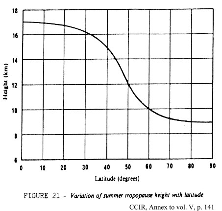
You see that the troposphere reaches to a height of 17 km near the equator, so expect the best troposcatter conditions in the equatorial zone. This argument is backed by the CCIR curves for path loss in the equatorial zone, but is of little importance, since you hardly are going to let the equator be your next /P QTH.
Much more interesting is the variation of the troposphere height 3-400 km from your QTH. The weather service (MET office) of a major airport near you may provide information on this. What you are looking for is turbulence and irregularities as high up as possible. Jetstreams are strong winds about 10 km up and may just provide this. Also a more dense atmosphere will be able to scatter more, so a high pressure will enhance troposcatter conditions, particularly on the distances shorter than 500 km. Thunderstorms may have cumulus nimbus clouds reaching up to 11-13 km. Perhaps thunderstorms 3-400 km away from you will enhance conditions in that direction? Just do not expect miracles from troposcatter. Other forms of propagation provide miracles.
The most important source of information on the troposphere are MST radars, see a worldwide overview of MST radars at
http://www1.tor.ec.gc.ca/armp/king/radar/prof-urls.html There is one in Wales which transmits on 46,5 MHz with 160 kW peak to a 104x104 m antenna with a beam width of 3,3 degrees. Such a radar can measure lots of things in the Mesosphere, Stratosphere and Troposphere (thus the name MST) and most important some of the results are available on the internet, check http://www.aber.ac.uk/~mstradar/ and www.nerc.ac.uk/nss/mst.html The radar pictures shows that the scatter situation is often more complicated than the simple drawing I have presented above. Some of the radars provide an online picture of the ionization 80-90 km above the radar site. Here you can even see Es clouds and other forms of ionization, which could be useful for a QSO. Check http://www.irf.se/mst/MSTlatest.html as an example on this.
No. of scatters => antenna gain loss
The books write about ‘antenna gain loss’, an effect where more antenna gain may not to increase field strength. Lets us look into this effect in details to see if this applies to us. TS need high power and a big antenna, but not more than 30 dB antenna gain at each end according to the text books.
 High gain antennas will have less common volume of air to scatter the signal. Though the intensity of RF on each scatter cell increases with the square of the beam width, common volume and thus the number of scatters decreases with the cube of the beam width. The net result is, that an increase of 3 dB in antenna gain will not give a 3 dB increase in signal strength if the antenna gain at each end of the path is in the order of 25 to 30 dB or more. This is called antenna gain loss. Few of us have such big antennas for 144 MHz or 432 MHz, but for microwaves more than 30 dB gain is not uncommon. Luckily antenna gain loss decreases as the range increases over 500 km and at 1.000 km there is no antenna gain loss, as only the bottom of the common volume contains scatters. Thus antenna gain loss need not to be considered for real DX.
Airplane reflection or troposcatter
Airplane reflection has nothing to do with troposcatter apart from the fact that you may have difficulty in knowing which propagation mode is providing you with the QSO. It is my experience that some the stations 8-900 km away often pop up on 144 MHz only for 1 or 2 minutes and are then never heard again. This does not apply to the stations I know have eme capability, that is they have QRO and big antennas. They are constantly readable as long as we beam each other.
According to The VHF-UHF DXer, 1992, p.4-8, the signal strength of reflection from one Boing 747 in the right position is at:
|
300 km |
15 dB lower than TS |
|
600 km |
as TS |
|
800 km |
15 dB higher than TS |
|
950 km |
20 dB higher than TS |
Could be that quite a few of the longer DX QSO are caused by reflections from airplanes.
I think this table was calculated for 144 MHz. According to the information I have 600 km QSO’s can be made on 1296 MHz using airplane reflections with lower path loss than on troposcatter. An example is the regular Copenhagen-Stockholm QSO’s made on 1296 during the activity contests which seems to follow the airplane tables.
Greater range on 70 cm than on 2 m
70 cm may have greater range than 2 m, because:
a. lower noise level in the sky means you can take better advantage of a low-noise preamplifier in your 70 cm receiver
b. greater path loss is compensated by a larger antenna gain, given the same physical dimensions of the antenna
c. more frequent ducting because a smaller duct will do
Why do most amateurs then think that 70 cm has shorter range?
Troposcatter has the following characteristics at VHF, UHF and SHF:
If there are "good conditions" you will have even longer range with less equipment. Use the many special propagation modes when they are there. There are many possibilities:
Meteorological: - inversion
- ducting
Reflection: - earth moon earth, EME
- meteor scatter, MS
- airplane reflections
Artificial: - satellite transponders
Ionosphere: - ionosphere scatter, IS for 50 MHz
- sporadic E-skip, ES
- aurora
- trans equatorial propagation, TEP
- field aligned irregularities, FAI
8, January 1958, p. 12-18 ¬ the whole volume is 200 pages of interesting stuff on tropo- and ionoscatter
"Report of JTAC on Radio transmission by ionospheric and tropospheric scatter", Proc. IRE, January 1960
Leang P. Yeh, "Simple Methods for Designing Troposcatter Circuits", IRE Transactions on Communications Systems, September 1960, p. 193-198
W.E. Gordon, "A simple Picture of Tropospheric Radio Scattering", Transactions of the IRE, November 1954, vol. CS-2, Nr 3, p. 97-101
The scatter propagation Issue: Proc. of the IRE, October 1955, p. 1175-1298 ff.
R.G. Merrill, "Optimum Antenna Height for Ionospheric Scatter Communication", IRE Transactions on Communications Systems, March 1960, p. 14-19
R.G. Merrill, "Radiation Pattern in the Lower Ionosphere And Fresnel Zones for Elevated Antennas Over a Spherical Earth", National Bureau of Standards Monograph 38, 1962
Old books:
- Grosskopf, Jürgen (1970), Wellenausbreitung I
- Burrows, W.G. (1968), V.H.F. Radio Wave Propagation in the Troposphere
- David, P. (1969), Propagation of Waves
- E. Baur, Einfürung in die Radartechnik, ISBN 3-519-00106-3, Stuttgart 1985
- Roda, G (1988), Troposcatter radio links, ISBN 0-89006-293-5 ¬ quite good
- Reference manual for Telecommunication Engineering, Roger L. Freeman, ISBN 0-471-86753-5, New York 1985
I recommend some works of International Telecommunication Union:
- Reports of the CCIR, 1990, Annex to volume V: Propagation in non-ionized media, ISBN 92-61-04211-2, Geneva 1990 ¬ comprehensive, some 500 pages!
- 1992 -CCIR Recommendations, Propagation in non-ionized media, ISBN 92-61-04531-6, Geneva 1992, p. 237-245, Propagating prediction techniques and data required for the design of trans-horizon radio-relay
systems ¬ 9 pages with almost all you need to know about TS!
- CCIR Study Groups 1990-94, document 5/34-E, Prediction procedure for the evaluation of microwave interference between stations on the surface of the earth at frequencies above about 0.7 GHz. ¬ good overview of all kinds of propagation, that gives interference for commercial services and QSO's for us.
Amateur literature:
- Gannaway, J.N., G3YGF, Radio Communications, August 1981, p. 710-714 and 717. ¬ recommended, most amateur literature uses this as source.
- Gerzelka, UKW-Amateurfunk, 1981, München, ISBN 3-7723-6472-1
- The VHF/UHF DX book, 1992, Buckinghamshire, ISBN 0-9520468-0-6
- ARRL UHF and microwave experimenters handbook
- Jessop, G.R., VHF/UHF manual, 1983, ISBN 0-900612-63-0
A little advertising is coming your way also. My practical experience with troposcatter comes from contesting where propagation can be judged. OZ5W/OZ9EDR contest team tries to make DX QSO’s regardless of band conditions, but we need someone at the other end to make a QSO. Please try looking for OZ9EDR or OZ5W in major contests and 19-23H local time:
1.st Tuesday of the month: 144.280 SSB/CW +.305 8877/2x8874 2x18elm M2+2/4x9elm
2.nd Tuesday of the month: 432.180 SSB/CW 3CX800A/4CX400A 4x20elm+2x21elm
3.rd Tuesday of the month: 1296.180 SSB/CW OZ1BGZ 70 W at 4x37 elm JO65AP
4.th Tuesday of the month: 50.160 SSB/CW 2x8874 1kW 9elm /P JO55KR
We mostly have one beam to the south (DL and PA0) shortly after 19H local and to the northeast (SM and OH) around 21H local. Please exchange full 6-digit locator. We are in JO55UL or /P likely at JO64GX or JO55KR. Skeds may be arranged even via Email to SMS
[email protected] but remember only the Subject field is shown in the SMS.E-mail: [email protected]Phone: +45 46 78 77 67 GSM: +45 40 36 77 67 Fax: +45 46 76 10 67 Sri no packet, life is too short for QRP and 1200 bps! |
Snail: Palle Preben-Hansen Soderupvej 104 Aagerup Mill DK-4000 Denmark © OZ1RH |