(Click to zoom)
For this version of band filter, I have been inspired by an article of K4VX in QST september 1988 (click to download as PDF, about 1MB file size). These band filters are based on 3 or 5 sections Butterworth band pass filters, maintaining 50 Ohm impedance, and when built around toroidal inductors, can be made very compact.
(Click to zoom)
The big advantage is that these can be used for both RX (rejecting nearby 'out of band' signals) and TX (rejecting 'out of band phase noise' )
The performances of this band filter are very comparable with commercially available models (like DUNESTAR 540 - dowload specs as pdf 100kB or DUNESTAR 600 - dowload specs as pdf 300 kb)
With reference to the QST article quoted, what were the objectives for the project ?

(Click to zoom)
Looking into the performances (see table 2, page 19) of the filters proposed by K4VX, it is clear that :
Consequently :
|
|
|
|
| BAND | #sect | Q factor | C1 C3 (C5) | L1 L3 (L5) | Coil | C2 (C4) | L2 (L4) |
| 80m | 3 | 2.5 | 2.200pF | 12T | T80-6 spread 2/3 | 270 pF | 38T spread 5/6 |
| 40m | 3 | 2.5 | 1.200pF | 8T | T80-6 spread 1/2 | 110 pF | 28T spread 3/4 |
| 20m | 5 | 2.5 | 390pF | 7T | T80-6 spread 1/2 | 45 pF | 21T spread 1/2 |
| 15m | 5 | 3.5 | 560pF | 3,5T | Airwound 8mm form 10mm long | 28 pF | 15T spread 3/8 |
| 10m | 5 | 3.5 | 360pF | 3,5T | Airwound 7mm form 10mm long | 22 pF | 12T spread 3/8 |
Remarks:
Hereunder the performances of the filters, both measured 'naked', without band switching and with band switching (=final performances of the filter, including the relay switch)
|
|
|||||||||||||||||||||||||||||||||||||||||||||||||||||||||||||||||||||||||||||||||||
| Adjacent bands attenuation Filter only, without band switching |
Adjacent bands attenuation Including dual relay band switching |
|||||||||||||||||||||||||||||||||||||||||||||||||||||||||||||||||||||||||||||||||||
Construction tips & hints:
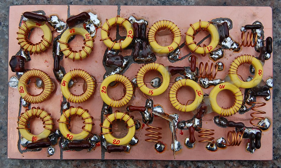
(Click image to zoom)
How to adjust the BPF sections ?
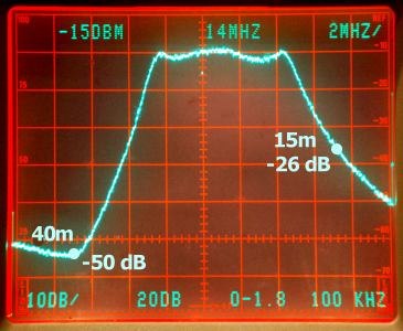
A spectrum analyser is the perfect instrument for adjusting this BPF. It is not 'a must', but will allow you to check the performances (crosstalk) and flatten any 'bumps' out of response curves...
 |
|||
|
BPF for 20m during
adjustment |
|||
As one can see from above figures, the ultimate rejection figures are very dependent on the quality of the relay band switch. Like in some commercial products (DUNESTAR Model 600 for example), I have used DIL miniature relays, these are indeed very compact and are capable of handling 100w up to 30 Mhz (non switching).
The very best DIL relay for this kind of applications are specially designed RF-Switching relays of AXICOM (click here to download specs as pdf, abt 2MB), they can handle up to 3A (whereas ordinary relays are specified as 1A max).
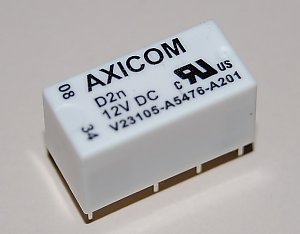 |
| AXICOM type D2n V23105-A5476-A201 |
What is the best switching configuration to avoid crosstalk between in- and output ?
I made several measurements and came to following conclusions ...independently of AXICOM or 'el cheapo' versions:

|
|
|
|
|
Using only one relay per BPF (Like DUNESTAR) |
Using two relays per BPF, Provides a very low crosstalk (-55dB) |

|
|
Dual relay' 5-bands switch with bypass (=blue relay) |
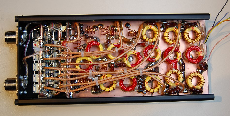
Hints for construction of performing relay switch:
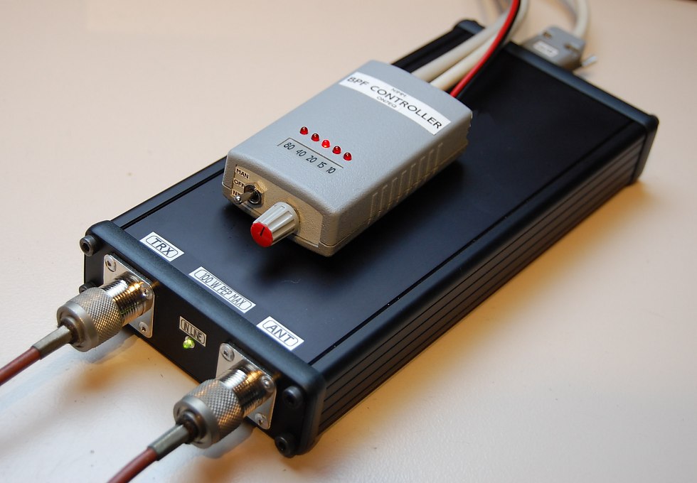
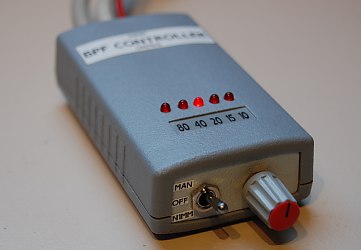
Relay switch control unit:
The relays can be controlled in several manners:
|
|
| Final assembly stage of BPF (click to zoom) |
It is recommended to use SILVER MICA capacitors, and tores from AMIDON.
I have ordered the components to build from PROFI ELECTRONICS KUHNA in Germany (see http://www.amidon.de) , as alternative several sources on EBAY are available, where I found as well the AXICOM relays.