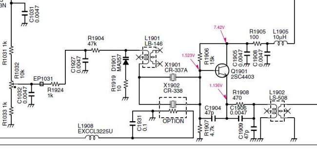
32 MHz master oscillator schematic diagram.
During some contacts in EME on 2m JT65B mode, I was aked by my QSO partners
if I was running an IC-9700 transceiver, because my frequency was drifting
... On the other hand, on 2m I had from time to time difficulties in making
QSO's in FT-8 mode, despite strong signals. I observed that the traces
of FT8 signals were not stable in the waterfall, instead of running
vertically, they were sometime distorted like 'banana's'.
In fact the absolute frequency error is not a big issue, as long as it is within the order of a couple of 100 Hz, it is the drift which is a 'killer' and absolutely must be eliminated to ensure optimal decoding (especially with low level signals like EME). So I decided to investigate and cure the problem !
The cause of the drift is the fact that the cooling fan of transceiver runs in TX mode, therefore the temperature in the cabinet is not stable, and frequency starts to drift.... this seems especially to be the case for the IC-9700, and as well the 746PRO.
What are the solutions and how effective are they? All the frequencies in the IC-746PRO are derived from a master X-tal oscillator (MO), located on the RF-board, operating at 32 MHz.
Fan running continuously : in my rig, I have since years the fan running slowly ( and silently! ) continuously, speed is increased automatically when going into TX
Reducing the TX power to minimize the internal heat dissipation: I already operate on minimal power, about 5 Watts out, as my LDMOS SSPA doesn't need more drive ...
Upgrading the standard X-tal part X-1901 / CR337A by option X-1902 / CR-338. In fact this CR-338 seems to be (as per circuit diagrams) a regular X-tal housed together with a heater, which keeps temperature stable (claimed as +/_ 0,5 ppm or about +/_ 70 Hz on 145 MHz). I have not tested this solution - but see below for possible shortcomings ...
32 MHz master oscillator schematic diagram.
Instead of CR-338, I mounted a
QH-4 Crystal Heater module (pdf)
of Kuhne (DB6NT) which I hand on hand and keeps the X-tal temperature
stable @ 40°C. For best thermal transfer, I smeared the backside of
module with a thin layer of heat paste, and in addition filled the
oscillator 'box' with cotton, like other hams have published .
The overall result was quite OK : after 15min warmup, drift was
less that 2 or 3 Hz during a transmission of 1 minute - like in JT65B
mode (measured with GPSDO controlled frequency counter). But at the end
of each 1 minute receive cycle, frequency was drifting by about 10 Hz,
in downward. direction (when the rig is warming up, frequency will go
down). I concluded that, despite the temperature of X-tal being kept
constant, other components of the oscillator might have a temperature
coefficient, causing an small - but adverse - impact on the frequency
stability.
Therefore, I decided to provide a possibility to sync with a GPSDO as the ultimate solution, while keeping the internal 32 MHz oscillator in service and 'on frequency', with minimal 'intrusions' or mods in the rig.
Suitable GSPDO's are for example the unit provide by LEO BODNAR, or if you hade a good ( = with low phase noise !) GPSDO of 10 MHz, you can go for a solution provided by Dieter DF9NP (see www.DF9NP.de) to generate 32 MHz from 10 MHz.
If an X-tal oscillator is 'stimulated' with an external signal which is close in frequency to the nominal X-tal frequency, it will follow as a 'slave' the external frequency - so it is a matter of coupling the external reference signal to the existing oscillator.
As a capacitive coupling seems quite risky in view of the microscopic SMD devices around the oscillator, I made the choice for an inductive coupling through L1901, which is connected in series with the X-tal. If required, this mod can still be undone ...
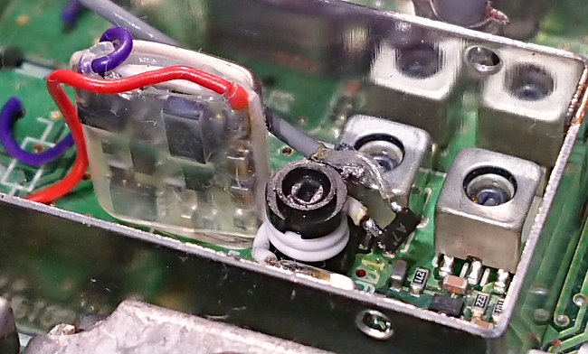
XTAL fitted with QH-4 Kuhne and L1901 with extra coil - note the BAV99
marked as 'A7'. Fill the tin box with cotton after the mod !
This was arranged with 2,5 windings of thin flexible wire, connected to a WiFi pigtail terminated by a SMA female long neck connector found in the junk box. Due to the presence of the 'piggyback' coil on L1901 and the coax cable capacitance, the oscillator frequency had to be slightly readjusted by the trimmer R1032 on back of the transceiver.
However, when connecting up a coax cable (lenght 60 cm or so) to the SMA connector, and thereby NOT injecting the external 32 MHz reference signal, the MO frequency will be altered - on 144 MHz this will be reflected as shifting some 400 to 500 Hz upwards ... this is due to the extra capacitance of the added cable. In order to cope with this, a low capacitance diode was added in series with the sync cable end and the extra coil on L1901. I used the 2 diodes in series of a BAV99 which will result in a maximum total capacitance less than 1 pF. The external signal (and coax) can now be switched on by having the diodes conducting with a current of 10 mA about. When the diodes are not conducting, the effect of connecting up an external coax is totally negligible.
Tested the level required to have the MO syn'ced with an external source and measured this as + 6dBm. To be on the safe side, let's say that +10dBm is required. Tested stability of oscillator with full RF output power on all bands, and at first sight it is all OK !
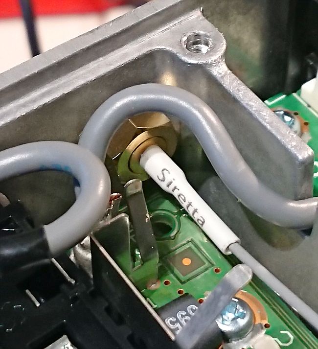
SMA female socket mounted next to KEY jack
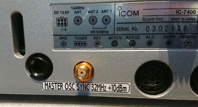
SMA socket view from outside on rig's rear panel
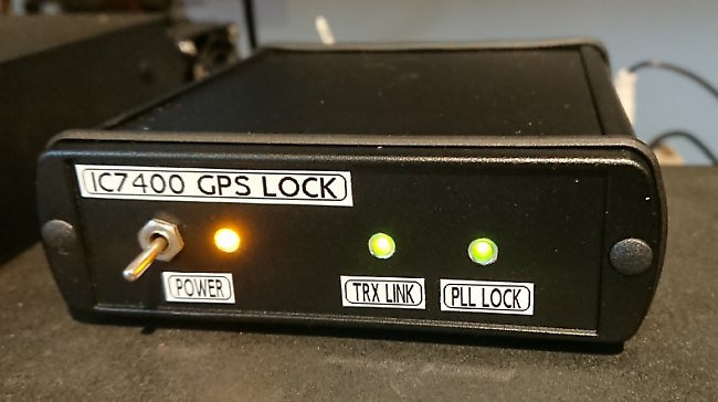
The circuit boxed - the 'TRX Link' LED indicates connection to IC7400,
the 'PLL Lock' LED indicates
10 MHz reference signal input present and 32 MHz output locked to it.
Good luck with the mods !