Sound card based multimeter
Updated Dec 25, 2008; program updated Dec 28, 2008.
Contents
- Preface
- Results of SB analysis
- Possibility of DC input solution
- Result
- The final solution
- SL-9950 USB sound card solution
- Notes for construction
- Features summary
Preface
PC sound card, standard component of practically all current personal computers,
consists, in minimum, of two parts:
Those parts are usually doubled as all sound cards are two channels - e. g. stereo devices. They may contain other parts, but from the point of view of analog to digital (A/D) signal processing they may not be as important.
Mixer is device joining analog signals from different signal sources into one which is delivered to A/D conversion. Important feature of current mixers is full software control of gain and level of all channels.
A/D converter is usually high precision 16-bit analog to digital converter with maximum sampling rate 44.1 kHz, or 48 kHz.
All (4 ;-) sound cards we've tested and analyzed have the same feature - all their line-in inputs (and others too) are insulated from DC input by condenser. The reason is, clearly, to set zero level of processed sound signal stable and close to zero. This is, however, a strong limitation for other use, for example for DC measurements.
The situation, fortunately, is not so bad as it seems...
Results of SB analysis
We've analyzed, with a good magnifying glass and ohmmeter, LINE IN inputs of
four different sound cards - three from Creative Labs, one from Manli:
Inputs of SB16, Audio PCI5000, AWE-64 and CMI8738SX, respectively, are on the Fig. 1.
Fig. 1: SB16, Audio PCI5000, AWE-64 and CMI8738SX LINE IN inputs.
As it can be seen, three inputs are very simple. Input of AWE-64 is a bit more complicated. It contains standard FET operating amplifier, but not condenser at the input. The condenser is at the output, however...
All four sound cards have DC default level at mixer input significantly high. The values displayed don't reflect reality. It was found, that it is close to 2.5V. Direct connection of external DC is not applicable. Is there a solution?
Possibility of DC input solution
There exists well known application of operating amplifier - differential amplifier. It's schematics (Fig. 2) is quite simple.
Fig. 2: Differential amplifier.
The output is joined with inputs by the formula:
The analysis of the formula shows, that at the output there can be defined DC level even in the case that U2 will be zero - provided appropriate signal will be delivered as U1.
A brief inspection of Fig. 1 shows, that AWE-64 already has operational amplifier. Good new! It is candidate No. 1. Assumed changes will be negligible.
Result
What is needed:
- disconnect noninverting input from ground,
- make tunable source of U1, one for both channels should be enough,
- with a piece of wire make a shortage between condenser pins,
- with running PC tune U1 to get appropriate DC level.
Fig. 3: AWE-64 input modification.
It works fine. With the device we did a few measurements. It was found that the maximum sensitivity is approximately +/- 100 mV. Based on +/- 5 V power it can be assumed that maximum input DC signal will be approximately +/- 2.5 V. Higher voltages must be decreased by hardware divider.
With operational amplifier on small PCB we checked SB16 and CMI8738SX too.
The final version had been made with CMI8738SX Manli sound card. Only reason
for selection was that it was cheapest and is currently available. Additional
to Fig. 3 the schematics contais -5V chip, as sound card has none.
The rest are a bit older models. The results of all sound cards were comparable.
The solution is not limited to AWE-64 and comparables. It seems any sound card can be modified provided small PCB with operational amplifier will be added. At the begining AWE-64 was chosen only due to fact it already has the (pre)amplifier. However for the final solution it was not suitable - in between mother board of home computer changed and ISA slot gone...
The final solution
To test, and even to use the device, one need some useful program. As a first choice we decided to get Konstantin Zeldovich's Winscope. It is complete, sophisticated and ... free. However, its use for more serious job is not very easy as it doesn't contain calibration feature and, what's most important, it doesn't allow AC/DC V/A measurements with numeric output.
To meet our needs we developed original program. It is two channel:
- oscilloscope,
- AC/DC V/A meter,
- frequency meter,
- VU-meter
To make it a real multimeter we equipped the device with manual range switch. Its construction is very simple:
Fig. 4: Manual range switch (one channel only).
The resistors used are standard ones, e. g. no special selection is needed - calibration will ensure the final accuracy. Resistor 1M is standard 0.25 W resistor, resistor 11M is old 0.5W one from stock. It may be difficult nowadays, far from vacuum tubes era, to get one. But who has stock... Anyway, it can be any in the range 5 - 15M, serial combination of smaller resistors too... Resistor 0.1Ohm is a small piece of some resistive wire of unknown origin (maybe from car power controller?) from the same stock.
No special components were used. Dual switch was constructed in small metal box with input bushings. It is connected with LINE IN input by standard shielded stereo cable. Switch takes very little space at the table, PC sits near the table, so no change in the organization in the room was needed.
It was created program to use all information available. It is quite complex one. As it can be seen from Fig. 5, it is dual beam oscilloscope-like device combined with AC/DC multimeter and frequency meter.
Fig. 5: Soundscope main screen.
- scope window
- channel controls panel
- multimeter & controls panel
The scope window has:
- width 11.6 ms or 92.9 ms depending on sweep range selection (see below),
- height +/- 3 depending on range switch selection (see below),
Single click on scope window activates image save dialog - it allows to save screen shots. Currently supported are BMP, GIF and JPG formats.
Below the scope window there is status bar displaying (sometimes) status messages.
Panel of channel controls on the right side of the scope window contains 2 identical sets of controls for each channel - A and B - (from left to right):
- zero level
- gain
- trigger level (below gain control)
Multimeter & controls panel contains (from top to bottom):
- multimeters
- sound device selector
- trigger control
- time base control
- operation controlls
Multimeter window contains two displays - larger and smaller ones - larger one displays voltage/current or raw data depending of calibration/raw data button status. Smaller one displays frequency in Hz.
At the right side there are range switch buttons. They are active only if soundscope is calibrated.
AC measurement is enabled by "Hz" button. When pressed, both windows - multimeter and frequency - display AC values.
Below those multimeters there is sound device selector.
The trigger control group consists of (from top to bottom):
- triggering enable/disable
- channel A or B selection
- indicator of active triggering (yellow=active)
Time base control contains 2 butons in group:
- fast - 1 ms/div
- slow - 10 ms/div
Data saving definition button opens small window for data saving options:
Fig. 6: Data saving definition screen.
It can be selected continual saving into regular WAV file format or timed sample data saving into special text file (CSV). Sampling period, capturing time and data file name can be set.
Right lower corner contains by control buttons:
- calibrated/raw display button
- start/stop button
- hold/release button
- start/stop data saving button
- about
- help
- program close
Program was created using Borland Delphi 6. No shareware or commercial libraries or components were used. To control mixer it was used excellent free mixer component developed by Vit Kovalcik. To display numeric values nice it was into Microsoft Windows installed LED display font - NI7SEG.TTF found somewhere on the Internet.
All copyrights of the program are owned by the authors. The noncomercial use of the program is free of any charge. All other use must be consulted with the authors.
Program runs under Microsoft Windows 2000, XP and 98. It successfuly runs at AMD K6-2 333MHz/64MB RAM. It may have problems on slower old machines.
Program is based on LINE IN inputs use. It is set to use two-channel 16-bit A/D conversion at 44.1 kHz sampling frequency.
Buffer size of the input sampling is 4096 samples, e. g. measurement frequency is 10.7 measurement per second.
Due to low sound card sampling frequency the highest frequency of the acceptable processed signal is around 10kHz. Higher frequencies are processed too, but the AC accuracy drops down.
Anyway DC measurements can be quite accurate, depending on calibration accuracy, of course and sound device A/D converter quuality.
The main domain of the device use should be, except of use as standard multimeter, DC and low frequency AC measurements.
AC amplitude measurements are achieved by software rectifying - the value displayed is close to effective value of the AC signal.
Frequency measurement is achieved by periods count measurement. As the measurement is sampled by 1/44 100 s, it is also measure of the frequency display accuracy. The smallest measurable frequency is around 20Hz.
Triggering is derived from channel A or B. There is no possibility to have triggered both channels. Triggering level can be set. Trigger level is not dependent on display zero level. Currently only positive levels can be set.
As the signal is sampled, e. g. not continual, the resulting triggered display is usually not fully stable.
Successful use of the program expects proper sound card setup. It is accessible via MS Windows Control panel -> Sounds and Multimedia -> Audio -> Recording setup. For more details check Microsoft Windows help.
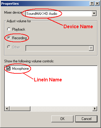
An example of sound recording setup parameters.
As personal computers can have more than one sound card, proper card selection and setup is prerequisite.
Hardware modification described in this article, provided properly set, does not influence sound card standard features in any way. The modified card can be still used the standard way.
Since the soundscope can be used as no calibrated, it's not its goal. To use multimeter functions it is necessary to calibrate all ranges.
Before calibration is started, it is suggested to measure linearity and sensitivity of the LINE IN input. It can be easily done using voltage calibration circuit described below.
To calibrate soundscope properly it is needed to prepare:
- variable voltage/current source 1 to 15V DC/1A,
- good potentiometer,
- good multimeter, preferably digital one,
- manual range switch properly set and connected with LINE IN input of sound card.
Calibration is three steps process. It consists zero level calibration, sensitivity measurement and measurement ranges calibration, which consists of three identical steps to calibrate voltage ranges and one step to calibrate current range (if used).
First step is zero level calibration. It requires disconnect any external voltages from inputs and connecting both ones with ground. Soundscope is switched to Raw data mode. Average value is read for each channel and written into program INI file.
Second step is sensitivity calibration. It requires connecting potentiometer with external DC voltage to both inputs. Soundscope is switched to "Raw data" mode. Potentiometer is set to minimum and slowly turning to get signal as close as possible to red line above (or belove) zero line. Voltage required and average raw value is read for each channel and written into program INI file. There is only one value for both channels. They should not differ in sensitivity, however.
To calibrate voltage ranges one is expected to use circuit according Fig.7.
Use of regulated power source is very convenient, anyway the calibration can
be sufficiently done using batteries as power source. In this case small lamp
should be used to limit current.
Current range is calibrated with the help of circuit on Fig. 8. It should be noted, that ground bushing is not used. This is possible only if the power source has ground insulated from common ground. If it is not available, battery with lamp should be used.
Fig. 7: Voltage calibration circuit.
Fig. 8: Current calibration circuit.
Calibration process expects to switch Soundscope to Calibrated mode and have all CalFactorR, CalFactorL values in INI file sections [Range1].. [Range4] set to "1". Calibration process contains following steps:
- select measurement range on range selector (the same in both channels)
- set corresponding range on manual range switch
- bring externam voltage/current to inputs
- set voltage/current level to be exactly identical with range switch value
- read voltage/current values displayed on both displays
- calculate CalFactorR, CalFactorL values and write them to INI file
Example:
DC input: 0.2V
Display A: 0.192V
Display B: 0.211V
CalFactorR = 0.2/0.192 = 1.0416666667
CalFactorL = 0.2/0.211 = 0,9478672986
Program doesn't write anything to the MS Windows registry anymore. All required information is now stored in the INI file. It is standard ASCII text file. To change values in the INI file it is expected to use ASCII editor, Windows Notepad is good enough. Use of Winword may produce non-ASCII file and program will crash.
Program INI file name is soundscope.ini and it resides in the same directory
as program file. It has following structure:
| [Program] | |
| Debug = 0 | If set to "1" it activates program log creation |
| XPlook = 0 | for "classical" Windows theme use "0", for parrot-like XP theme use "1" |
| [Devices] | |
| Device Name = C-Media USB Headphone Set | Selection of sound device to use, if not found, first one available will be used instead. |
| LineIn Name = Microphone | Exact name of input channel to use. Can be found in Control panel - Sounds and Audio Devices settings. It is very important to set correctly, othervise program will not work |
| [Calibration] | |
| Zero left = 0 Zero right = 0 |
Raw average values of each channel |
| MaxLevel = 12480 | |
| MaxVoltage = 0,117 | |
| [Range1]..[Range4] | |
| LabelL = 0.2V, LabelR = 0.2V |
Range for channel A and B respectively. It is both label for range switch and internal calculations parameter. |
| CalFactorR = 1 CalFactorL = 1 |
Correction callibration factors. Before calibration is dome it is "1", after calibration it changes. Never set "0", othervise program will crash. |
| [Capture] | This section contains parameters written by program alone. Don't change any of them. |
| NameOfFile =captured.csv | |
| SamplingType = CSV | |
| CaptureTime =60 | |
| SamplingPeriod =1 | |
| TimeMeasure = min | |
| [Visible] | This section contains labels used for display. Translation to other language will translate user interface. |
Notes for construction
There are no special components used, except 11M resistor in switch. However silicon diodes at the input should be fast ones and should have very high resistivity. 1k resistor conducting signal to them and LINE IN should be as small as possible - its function is to be fuse. It should burn to prevent the input from overloading. Diodes should bear the "burning" current, of course.For soldering at the sound card microsolder is needed. Transformer solder must be avoided. A good lens or glasses and a certainty in hand may be needed too...
Be careful when disconnecting input pins from ground (provided sound card has preamplifier already). SMD chips are quite fragile!
We glued small piece of universal PCB carrying additional components close to the LINE IN input. All joins we did with insulated thin copper wires.
The overall view of the experimental prototype can be seen on Fig. 9.
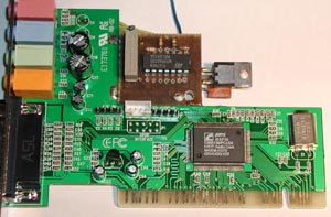
Fig. 9: Prototype view.
Features summary
| sampling frequency | 44.100 Hz |
| measuring frequency | approx. 10.7/s |
| measuring ranges | 0.3, 3, 30V and 3A |
| accuracy | better than 1%*) |
| type of measurement | AC and DC |
| maximum input frequency | 22kHz |
| working input frequency range | 20Hz - 10kHz |
| input resistance on voltage ranges | 333kOhm/V (100k, 1.1M, 12.1M) |
| input resistance on current range | 0.1Ohm |
| data saving file format | WAV or CSV |
| sampling times | continual, 1/4, 1/2, 1, 15s, 1, 5, 15, 60min |
| saving time range | 1s - 9999min**) |
**) 1s captured WAV file has size 176kB, 1 hour captured WAV file has size 635MB!!, an attempt to capture 9999min WAV file will fill your hard drive for sure...
This is
visit from Aug. 23th, 2009.