|
Hardware Interface
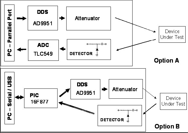
Two different design of hardware interface can be connected:
|
Option A: the hardware is connected to the PC via the parallel port (LPT).
The program directly drives the DDS unit and reads the output from the AD/C.
Option B: the DDS unit is driven by a PIC. The program interfaces via the
serial port the PIC sending commands and receiving back the samples. The AD/C function is implemented by the PIC.
|
Sweep v2.0 can connect the following devices:
| |
Project name/Author |
PC port |
Description |
| 1 |
Antonio Alfinito, I2TZK |
USB |
A PIC 16F877 controls an AD9951 DDS. The generator
can be used as standalone without PC |
| 2 |
Wobbler by Peter Halicky, OM3CPH |
LPT |
A "wobbler" project with the AD9851 DDS |
| 3 | MiniVNA by IW3EHW |
USB | An Antenna
Analyzer used as sweep generator |
Interface 2 � DDS/AD/C connected to the LPT port
Please refer to wobbler project on this WEB site for any technical detail
related to the basic project by Peter Halicky, OM2CPH and the additional solution
implemented by Tomas, OK1UTS.
Any block can be implemented with a different circuit style, so far if a different
DDS device like the AD9951 and a specific xtal frequency/clock multiplier will be
used, the appropriate parameters must be initialized with the "SetUP/Configuration"
menu.
The table lists the parallel port pins connection and the wiring managed by the program
| LPT pin name |
DB25 pin number |
Block |
Signal description |
| D0 | 2 | DDS, AUX1, AUX2, POT | Data out |
| D1 | 3 | DDS | Clock |
| D2 | 4 | DDS | Chip select |
| D3 | 5 | DDS | Reset (AD9951 only) |
| D4 | 6 | POT | Clock |
| D5 | 7 | AUX1, AUX2 | Clock |
| D6 | 8 | AUX1 | s/r clock |
| D7 | 9 | AUX2 | s/r clock |
| Paper End | 12 | AD/C | Data in |
| Strobe | 1 | AD/C | Clock |
| LineFeed | 14 | AD/C | Chip select |
| Reset | 16 | | Sweep syncro |
AUX1, AUX2 : array of 8 output (simulate 8 bistable buttons for a stepper attenuator)
POT: I2C bus, drives an I2C compliant chip (digipot for amplifier gain control)
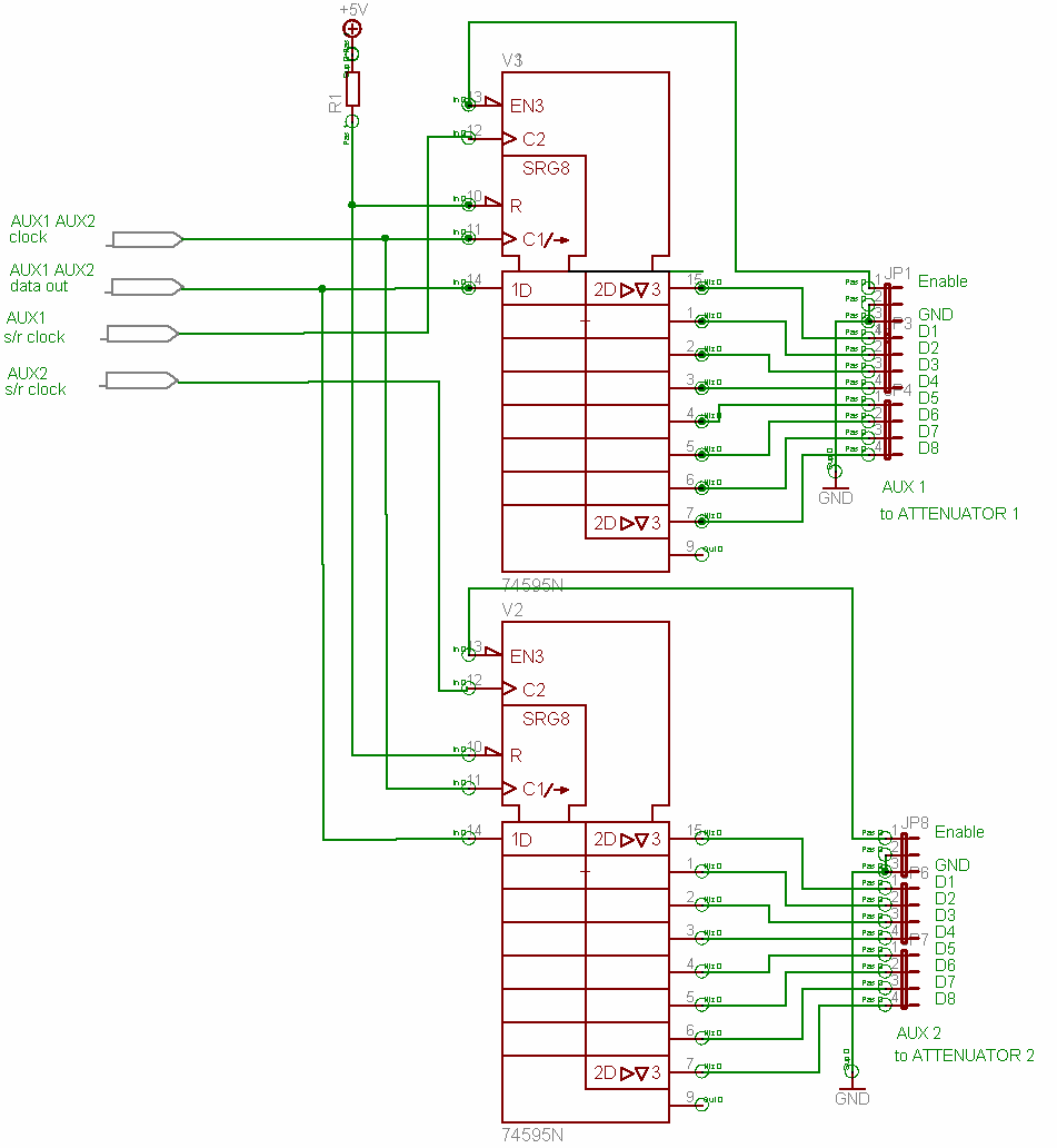
The following figure is a recommended additional circuit for a safe interface
between the PC parallel port and the DDS/ADC implementation.
|
In order to minimize the number of LPT pins, a simple circuit driving a shift
register SN74HC595 is requested to interface the AUX1 and AUX2 buttons array.
Positive or negative output when a button os pressed, can be selected configuring the AUX frame.
|
|
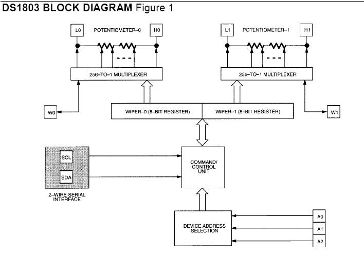
The slide bar of the frame AUX2 drivers the I2C bus at Pin 2 data and Pin 6 clock of the LPT port.
The device DS1803 is used, this component implements 2 digital potentiometer.
Program controls a the same time the two wipers, so both or just one potentiometer can be used.
|
The default address of the device is A0 = 0, A1 = 0 A3 = 0.
Any time the slide bar cursor is moved, the following command sequence, is sent to the I2C bus:
Start
Write control byte = 80 (*)
Write command byte = 175 (*)
Write value = slide bar cursor position
Stop
(*) can be changed editing the [Aux2] section of the sweep.ini file
A Syncro signal is also availabe at the Pin 16 Reset of the LPT port.
The signal is issued at the beginning of each sweeping cycle, this can be used
to to syncronize an oscilloscope or with few additional components to generate a
ramp signal during the sweep cycle.
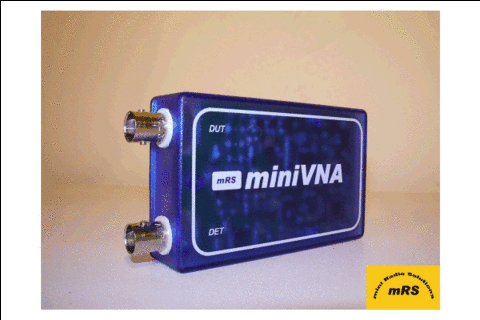
Interface 3 � MiniVNA connected to the USB port
This device was primary designed as an Antenna Analyzer.
For any detail, please visit: http://www.miniradiosolutions.com
|
|
With a minimum approach it is possible to use this device as a Sweep Generator |
Connect the input of the device under test to the miniVNA generator output "DUT"
and his output to the "DET" input.
During the sweeping cycle the program reads back the detector output.
The "angle" or the "return loss" samples can be also acquired, if needed, the
parameter "AD/C Channel" of the section [Config] of the sweep.ini file can be edited as follows:
| AD/C Channel | Sample returned |
| 1 | angle |
| 2 | return loss |
| 3 | detector |
The default value from the Sweep.ini file are:
;--------------- miniVNA --------------------
[Interface3]
DDS Device=AD9951
DDS Multiplier=16
DDS Xtal freq=25000000
DDS Max freq=180000000
DDS Min freq=100000
DDS Offset=0
ADC Device=10bit
ADC Offset=0
ADC Step=0,00175
ADC Channel=3
| 
