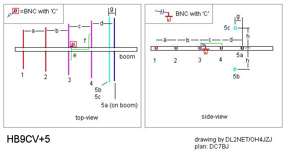
(plans after DC7BJ)
The HB9CV+3 is a fullfeeded directional antenna with 2 active plus 5 passive elements. One might call this array "HB9CV-Yagi". This adds about 4 dBd over the pure HB9CV and eliminates the squint of a classical 2-element HB9CV.
Regarding the fact that the design uses three(3)reflectors is rewarded with a very high front/back ratio. This is extremly useful for direction finding.
Unforetunately I can't give any performance feedback because I have not built this version of the HB9CV yet. Considering the great success of my HB9CV+3 version it might be working as well as it sounds!
Dimensions:
|
element:
|
remarks:
|
435 MHz
|
|
length (mm)
|
||
|
1
|
director 2(passive) |
280
|
|
2
|
director 1(passive) |
284
|
|
3
|
HB9CV (active)
|
324
|
|
4
|
HB9CV (active)
|
342
|
|
5a
|
reflector 1 (passive)
|
378
|
|
5b
|
reflector 2 (passive)
|
385
|
|
5c
|
reflector 3 (passive)
|
385
|
|
between:
|
435 MHz
|
|
|
spacing (mm)
|
||
|
a
|
element 1+2 |
120
|
|
b
|
element 2+3 |
125
|
|
c
|
element 3+4
|
90
|
|
d
|
element 4+5a
|
85
|
This type of matching is called gamma-match. A 50-ohm coaxcable can be connectet straight without a balun. Easier to handle than Yagis. But it is recommendable to insert a capacitor in series to centre conductor and the feeding point of the gamma-match. This is necessary to minimize the SWR.
|
@ element
|
435 MHz
|
|
|
length (mm)
|
||
|
e
|
3
|
52.5
|
|
f
|
4
|
60
|
Spacing of the gamma-match to elements and boom is 3-4mm.
Note that the triple reflector array is not mounted on a straight line. Both off-boom allocated reflectors are shifted 10mm horizontally (towards beam direction) and about 89.4 mm vertically above/below the boom.
|
Remark:
|
435 MHz
|
|
|
lenght (mm)
|
||
|
g
|
10
|
|
|
h
|
89.4
|
To connect the aerial to an 50-ohm coax-cable fix e.g. a BNC-flange-connector at the intersection of element 3 and the boom. Use a 5-10pF trimming capacitor - as seen in the drawing - to adjust minimum SWR. Replace the trimming capacitor with a fixed capacitor (remove + measure carefully) to guarantee long-time stability and weatherproofness.
HOME TOP (by DL2NET/OH4JZJ Sept.2000)