
This page is based on several magnicificant homepages available on the net.
My credits to those om's/DIY's who did extensive development work on this subject!
This page should make it easy to copy the helix with same parameters and to compare it to other designs. Feedback welcome!
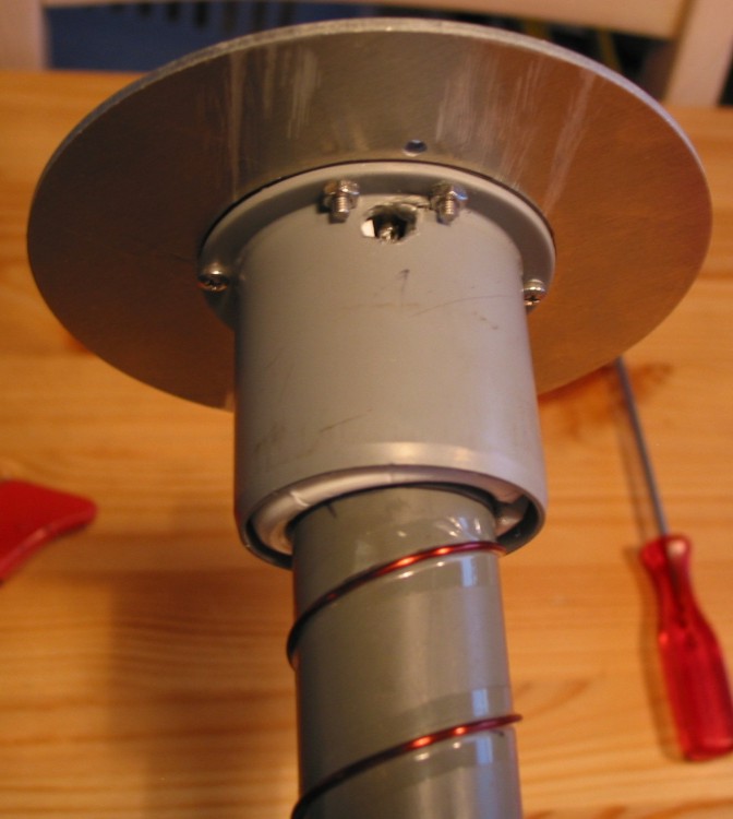
The final "product", an 18 winding HELIX, fully weather protected. (click to enlarge)
All parts sum up to less than 30 € with a performance over at least 2.4km!
Like for any other DIY projects the list of required tools is kept to a minimum. You are fully responsible for your own doing!
Disclaimer:
I will not take any responsibility for destroyed transceiver equipment, leaking sinks due to missing drain pipes or angry neighbours because of pointing sewer pipes toward their houses, caused by YOUR and only YOUR selfmade HELIX!
| Qty: | Partname: | Misc. description: |
| 1 | Aluminium disc, 120mm in diameter, 2-3mm thickness | Alloy: AlMg3 |
| 1 | Standard drain tube, 50mm outer-diameter, 500mm long | UPONOR HTP PP 50x1,8 SN4 B |
| 1 | Standard drain tube, 32mm outer-diameter, 490mm long | UPONAL CPVC 32x1,8 HT |
| 3 | Plastic spacer rings, inner-diam. 32mm, outer-diam.49mm | |
| 1 | 50mm Pipe endcap | |
| 1 | Standard 50mm Drain tube end-cap | UPONOR xxx |
| 1 | N-Flange connector, Z= 50ohm | |
| 11 | M3x15mm, V4A bolts | |
| 11 | M3 V4A nuts | |
| 11 | M3 washers V4A | |
| 1 | M5x15mm V4A bolt | |
| 1 | M5 V4A nut | |
| 2m | Enamelled copper wire 1,2mm diameter | |
| 10cm | Copper tape, 20mm wide (for impedance transformer) | |
| Silicone for sealing (Outdoor approved!) |
According to [3] I used HelixCalc [2] with a frequency f = 3620 MHz, diameter d= 3.2mm and Scalar = 0.27 to correct the shortening factor introduced by the PVC material of the center tube. You can download the HelixCalc from Jasons homepage [2] or use this two PDF-tamplates.
 HelixCalc by Jason
Hecker
HelixCalc by Jason
Hecker
Remember to disable any scaling options while printing the pages! Paper format is A4
The centre pipe (32mm) has to be cut to 490mm in length, since the pipes come in standard lenghts of 500mm. Using the 10 windings template you can choose freely how many turns your Helix will be consisting of. In this example 18 turns using two printouts. After carefully taping the paper onto the 32mm pipe I used a sharp carpet cutter knife to transfer the helix spiral from the paper onto the plastic surface of the pipe. This helps to accurately wind the copper wire around the pipe and the fine cut will actually guide the wire preventing it from slipping. Additionally it is secured with a thin self-adhessive tape. The windings reach from END-TO-END, excess wire will be cliped off later. (See section 2.x "Impedance transformer")
Tape the reflector template printout to an aluminium sheet metal. Drill and/or file all holes accordingly and at last cut out the 120mm disc with a fret saw. One can also use a rectangular reflector, works as well. Hint: Use Isopropanol-alcohol to cool and lube the sawing blade and drills, AlMg3 stucks easily to cheap tools if cuted "dry".
Accurately drill a 5mm center hole into the endcap's backside and attach it to the center hole of the 120mm aluminium disc. Now it's fairly easy to drill all the other holes without additional markings. A 10mm side hole has to be drilled/filed in order to be able to solder the N-connector's center conductor to the impedance transformer (Copper tape). Check the images.
Cut a trinagular piece from the copper tape with dimensions as below.
![]() Impedance transformer
after [2]
Impedance transformer
after [2]
The 20mm vertical copper wire reinforces the design which might otherwise tear the thin copper tape easily. Secondly, soldering it to the N-connector is far more easy! (see X-ray images in the gallery)
See images for details.
Here a skematic drawing of the design.
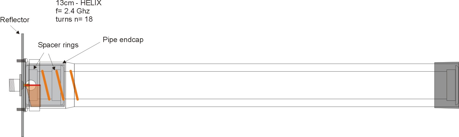 Schematic drawing
Now assemble all parts together. Attacht he inner pipe to the reflector. Solder the center conductor to the N-connector. Put the outer protection tube in place, if neccessary. That should be it.
According to [3] I used a similar measurement setup to be able to compare the performance of this helix.
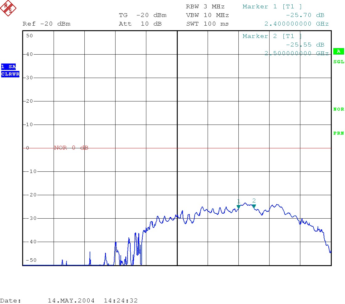
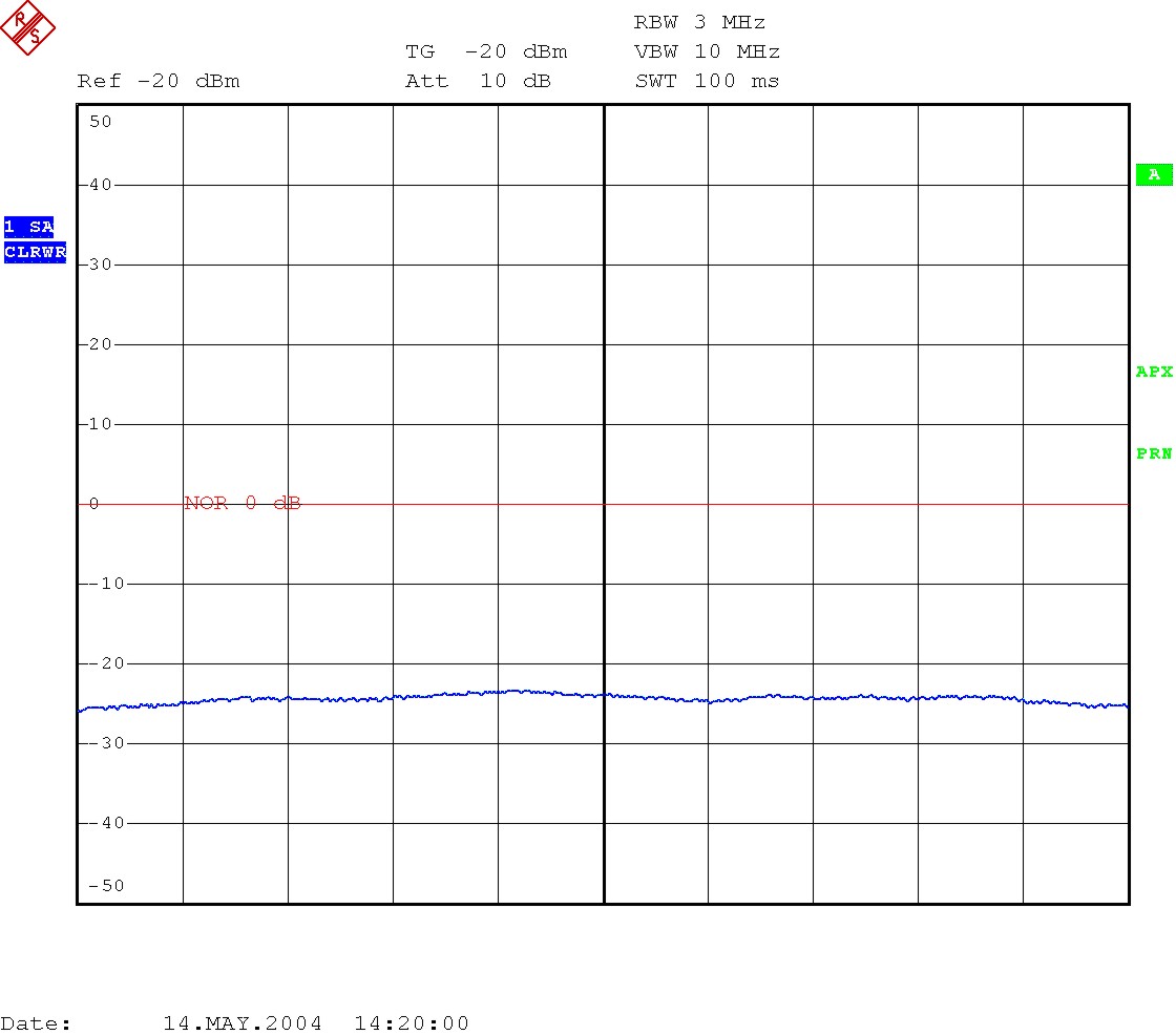
Two identical, 18 windings Helix antennas were fixed at a distance of 3.0m. One connected to a tracking generator, the opposite one to a spectrum analyser/test receiver. Cable losses are normalized so the loss does not appear in the following two diagrams.
Test equipment used: R&S ESPI3 Spectrum Analyser/Test Receiver with Tracking generator option up to 3GHz.
 |
|
|
Transfer characteristics from 1.0-3.0 GHz Marker1 at 2.4 GHz, Marker2 at 2.5 GHz |
Very linear from 2.4-2.5GHz
|
There was no SWR-bridge available yet, so no SWR-measurments could be performed.
If someone has a stripline PCB-layout for a 2-3GHz SWR-bridge terminated by 50ohm, it would be possible to test the SWR.
An outdoor test was carried out to verify the antenas real performance.
The test setup used two identical helix antennas attached to WLAN equipment through 0.5m homemade pigtails, consisting of RG-58 coaxial cable with an R-SMA and N-connector.
The first antenna is attached to a D-LINK DI-514 WLAN Router. Height over ground, around 4m.
One the other side using a D-Link DWL-810 WLAN/LAN Bridge attached to a notebook . Height over ground 1.0m. All devices battery powered.
Direct sight between both devices is slightly shadowed by the branches of one tree with no leafs yet. The notebook is pinging continiously with 512bytes, and response times of 5ms were measured during the entire test, from 0-2400meter! No Bit Error Rate test (BER) test was performed yet.
Does anyone know good software toos to test links? Freeware of course!
Distance covered: 2.4km At this point we stopped the test because we were on a small rowing boat and the weather became stormy...Next challenge is a 7.24km link from an island-hill.
![]()
Helix tip with spacer and tape securing the windings.
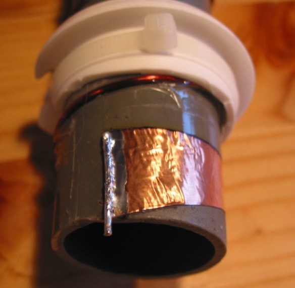

![]()
Copper tape with re-enforcing copper wire. Spacers added and secured with cable tiers.
 Reflector. Soldering hole for center conductor.
![]() Ready assembled helix coil.
Ready assembled helix coil.


Reflector backside and sideview (with protective pipe)

Test without protective pipe.
Outdoor version. Loss induced by the outer pipe is negligible.
Being blessed to have access to a real-time x-ray equipment I took some images for fun.
 |
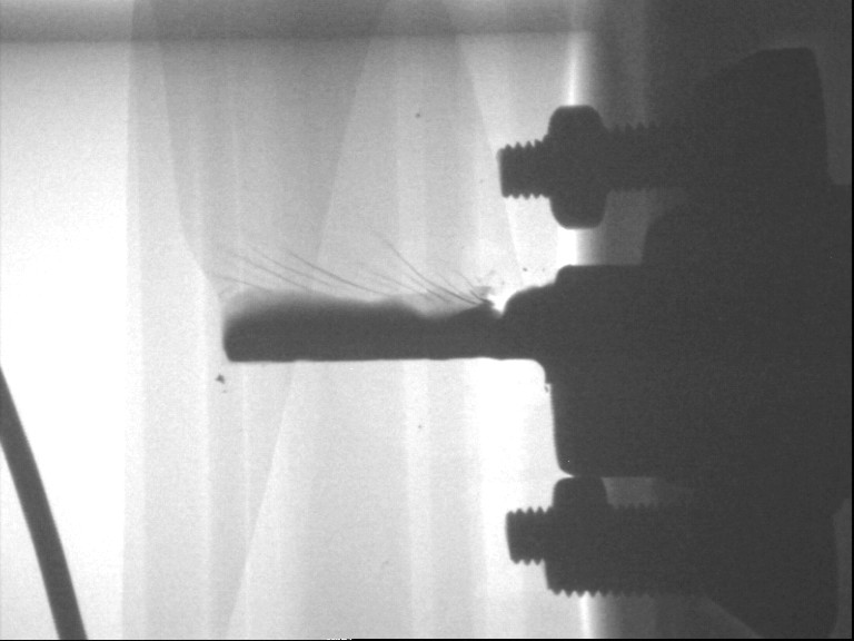 |
| Helix 1, perfectly attached | Helix 2, torn copper tape due to stressing while removing the outer protection pipe. Fixture was improved by adding a second spacer ring. |
1. Initial inspiration:
http://www.saunalahti.fi/elepal/antennit.html - Martti's WLAN pages
2. Superb construction details:http://www.wireless.org.au/%7Ejhecker/ - Jason Hecker
3. Improved design for dielectrical loaded HELIX:
http://www.qsl.net/pa0hoo/helix_wifi/index_eng.htm - PA0HOO, Improved Dutch HELIX