- final Ilmari Bandplan
for the 2007 flights (Word Document, 41k)
- final Ilmari Bandplan
for the 2007 flights (Adobe Acrobat PDF, 24 k)
- Ilmari Data Sheet (Word Document, 57 k)
- Ilmari Brochure (Word Document,
85 k)
- Ilmari Operation Manual
(Word Document, 23 k)
- Ilmari-2003:n workkimisohjeet, alustava
muistiinpano (in Finnish)
- mietteitä lineaarisuudesta ja HELAPS-tekniikasta (in Finnish)
- Ilmari-2003 simulator virtual launch daily at 1500 UTC, for e.g. testing tracking software etc. (by OH2JBB)
- the tracking s/w, also by OH2JBB, takes real daily upper wind and local sonde data for estimating the drop zone
- if you don't have APRS tracking software, you may try this for following the virtual balloon (Java by OH6VM)
- example: screenshot (60k) of the first virtual launch (grabbed by OH6FT of the Airborne Ilmari Search Team)
- provisional data of the RF payloads on board the Ilmari balloon
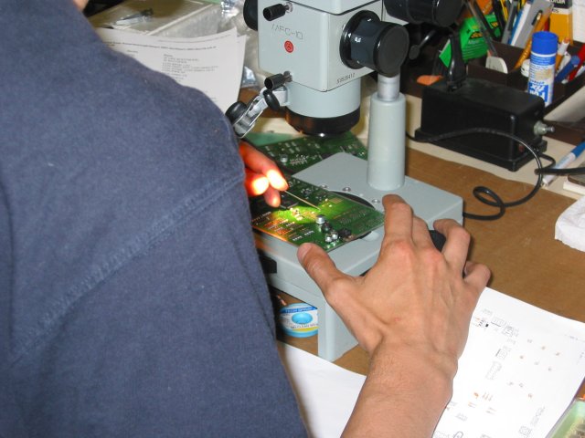
- Indoor Housekeeping Unit (by OH1MQK) under construction (OH1JJC (55k) at the microscope)
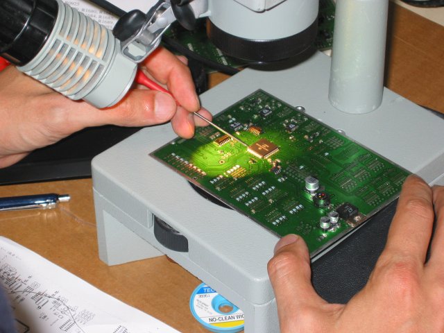
- closer view (54k) of the IHU board under work (manual SMD soldering by OH2JMS & OH1JJC)
- the 100 pin CPU is very carefully soldered in place and inspected (62k) before applying DC
- IHU board top side (77k) view, almost fully populated
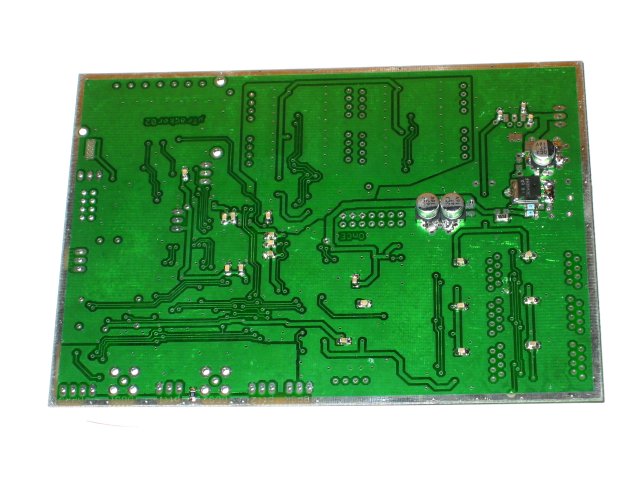
- IHU board bottom side (56k) view, almost fully populated (passed the DC test without smoke)
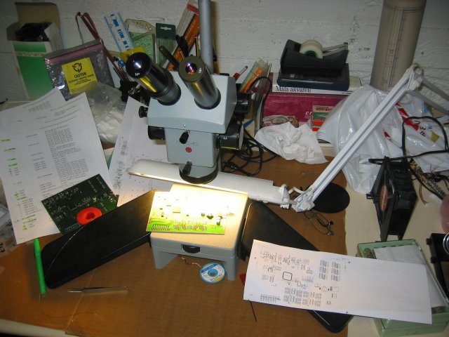
- the required working environment (63k) for about 20 hours or so for populating one board
- a schematic diagram of the balloon system in flight configuration, (30k) to give an idea of what will be on board
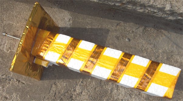
- here is some info and photos of the Ilmari parachute designed and produced by Jari, OH3UW
- here is the block diagram (15k) of the Ilmari-2003 payload system
- block diagram for the transponder (36k), translating from 2 meters to 70 cm.
- pinout of the + 10 dbm output transponder (28k) module
- pinout of the +10 dBm in/+30 dBm out transponder SSPA (8k)
- pinout of the IF command receiver (8k) module
- this prototype is using more traditional technology, but will be followed with a HELAPS design later
- the transponder is frequency inverting to simulate RATS-SAT requirements :-)
- also, to give you an idea of the bandplan, here is the prototype (13k) bandplan
- the transponder bandwidth will be limited to about 38 kHz using an ultralight (3k) XTAL bandpass filter weighing only 7 gr.
- this is the basic response (4k) of the DTMF command receiver bandpass filter
- and a zoomed view of the passband (4k) response and width of the command receiver filter
- some 1970 era feedthrough PI lowpass filters (9k) are proving ideal for RF bypassing
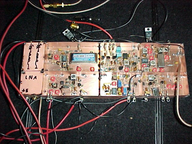
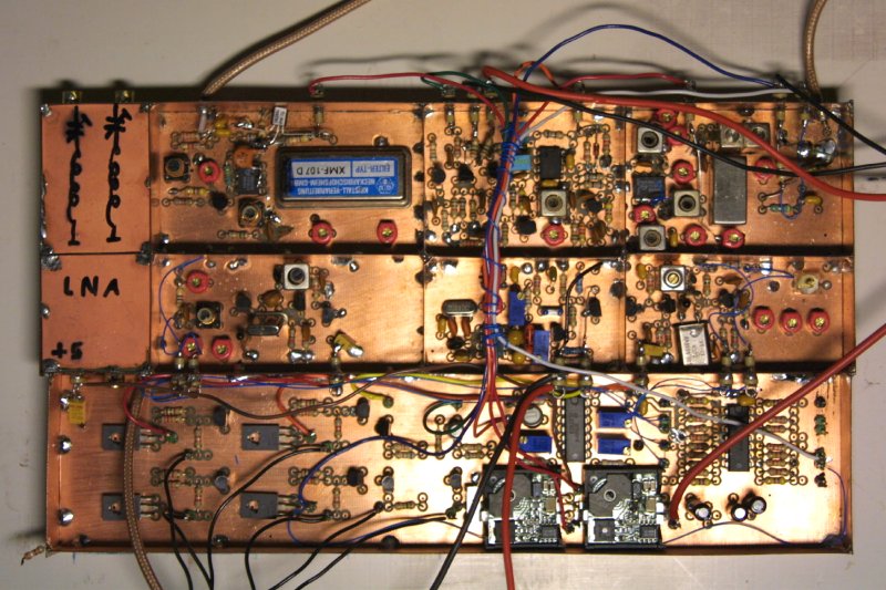
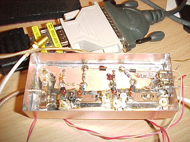
- the transponder hardware viewed from the component side (96k) before shielding (TRX produced by OH1LRY)
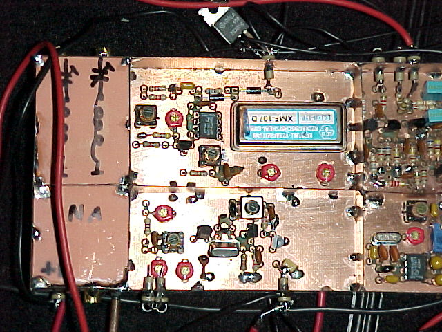
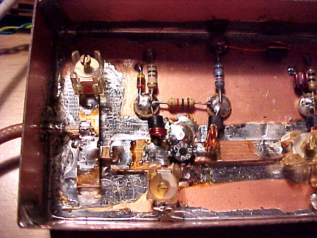
- closer view of the VHF input (107k) circuitry, IF, ALC, 400 bit/s BPSK beacon etc.
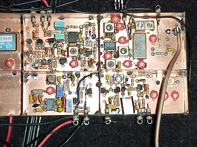
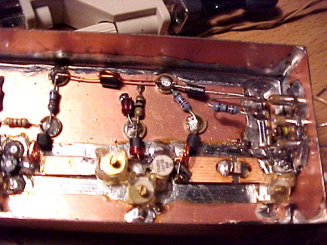
- closer view of the UHF driver (122k) output circuitry, ALC etc.
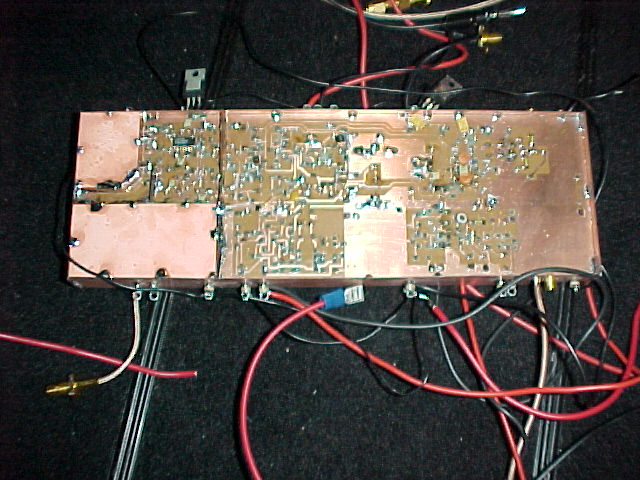
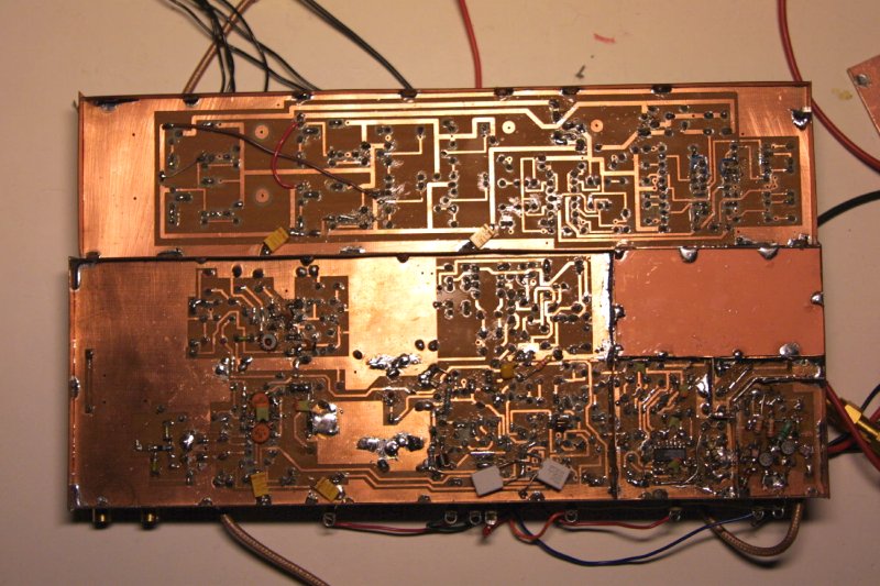
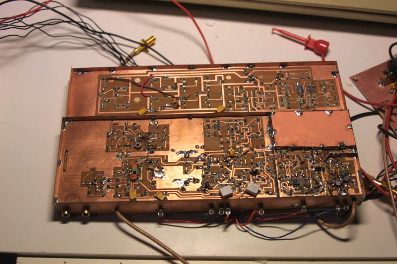
- overall view of the transponder PCB reverse (80k) side before shielding
- and a view of the transponder accompanied with the PSU/M&C interface board (107k), from the copper side
- view of the transponder with PSU and M&C interface (124k), component side
- and a photo of the interface side (96k) of the module
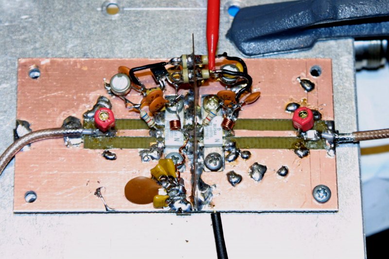
- FET's have proven to exhibit best gain/linearity/efficiency, so this (95k) is the current prototype PA (design: OH1LRY)
- soundclip: the Ilmari-2003 400 bit/s BPSK beacon (64k), live on the 70 cm downlink (fast ALC)
- soundclip: CW (209k), live, over the Ilmari-2003 transponder, VHF up, UHF down (fast ALC)
- soundclip: SSB test QSO (421k) over the Ilmari-2003 transponder, VHF/LSB up, UHF/USB down (fast ALC)
- transponder exciter dynamic range test results
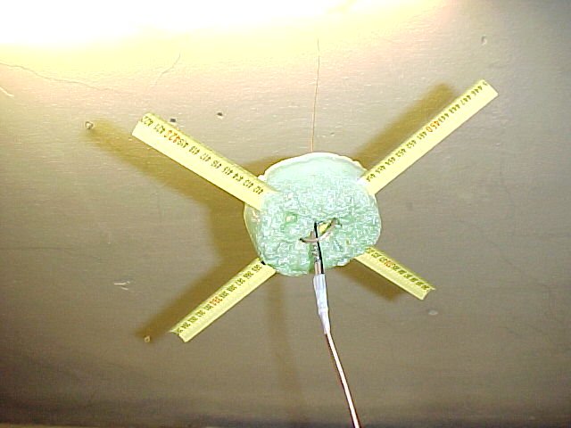
- the transponder TX antenna prototype (42k) yields good matching
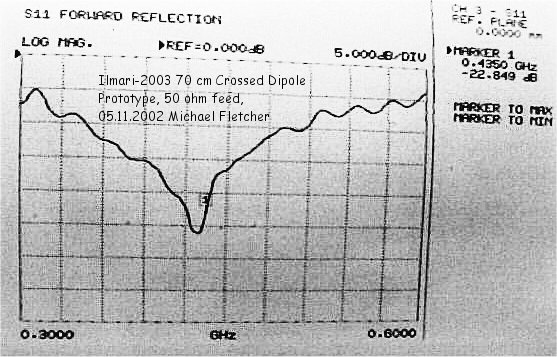
- measured return loss (59k) of the TX system crossed dipole antenna prototype
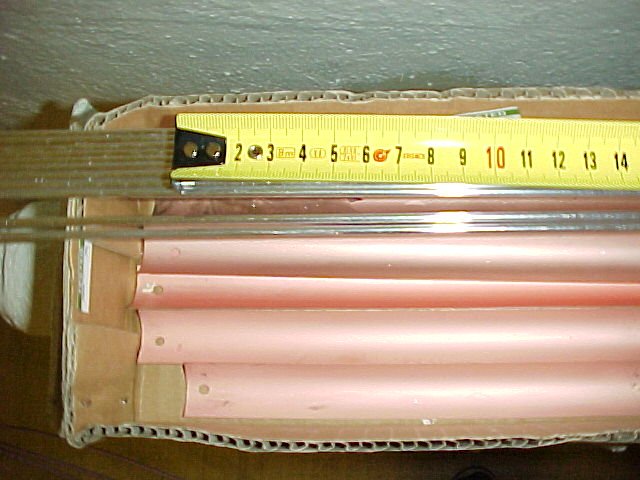
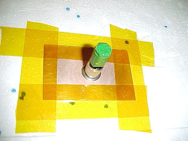
- the flight antenna material will be copper plated (58k) stainless steel tape rule
- flight model 70 cm crossed dipole embedded in polyurethane for stability, return loss (12k) after tuning
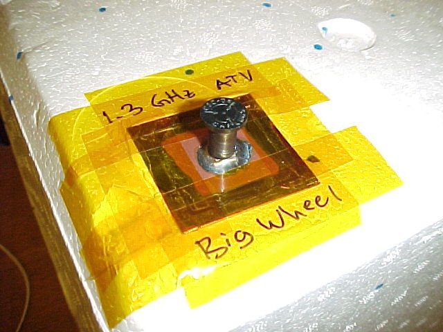
- in the above photo the 2 and 3 mm aluminium will be used for the 1.3 GHz Big Wheel and 70 cm APRS vertical
- formula (1k) for calculating accurate lambda/12 transformer length (from Darrell Emerson)
- configuration of lambda/12 matching transformer (2k)
- application of the transformer for matching two parallel dipoles (4k) to 50 ohms
- the final configuration of the crossed dipole (7k) system with 50 ohm feeder
- cable impedance formula, cable velocity and epsilon for PTFE
- and here is some more info on calculating cable impedance related numbers
- radio horizon for a balloon bearing transponder at heights of 0 ... 2000 m (12k)
- radio horizon for a balloon bearing transponder at heights of 0 ... 50 000 m (13k)
- estimated radio horizon map (31k) for altitudes of 5, 10 and 25 km (example of launch from KP21KK)
- the formula (3k) for calculating 4/3 refraction index influenced radio horizon (for normal conditions)
- prototype circuit diagram of the transponder 9 V PSU (this one using an NPN switch)
- prototype circuit diagram of the transponder 9 V PSU (this one using a PNP switch)
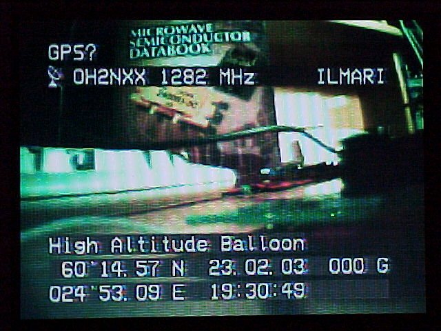
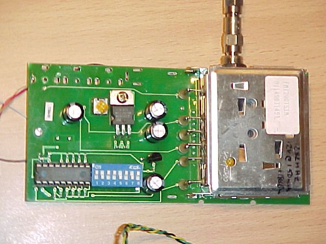
- the FM ATV television transmitter (71k) before packaging, tuned for 1282 MHz
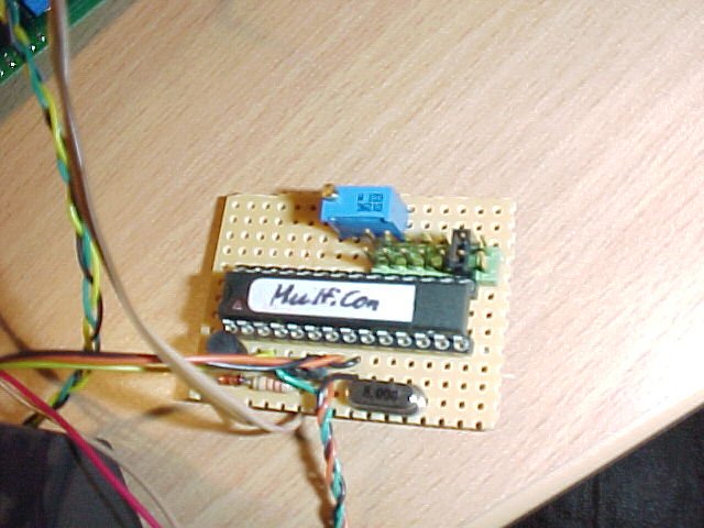
- the on board GPS receiver NMEA code is processed (58k) with this module by OH2LAK
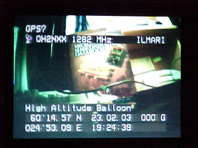
- this location data is then overlayed (66k) on the camera video
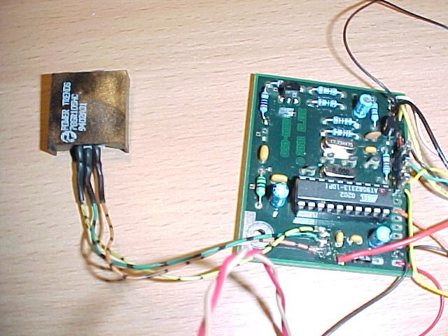
- overlaying is accomplished with this OSD module (75k) from DL1IE (12 V supplied by SMPS module)
- for testing the GPS live in my basement workshop, I had to construct a GPS repeater (8k)
- the ATV exciter (50 mW) drives this two stage PA (84k) to over 1 Watt, designed by OH3UW
- the intermediate amplifier is a BLU98 (93k) salvaged from a junked NMT radio
- and the final amplifier is a BLV91 (84k) with a similar history
- here is the circuit drawing of the dual stage SSPA (19k) by OH3UW
- this 1282 MHz, 1 Watt signal is fed to a Big Wheel molded in polyurethane for rigidity (antenna return loss, 11k)
- in between the SSPA and the antenna is a low pass filter to kill harmonics (return loss of antenna with LPF, 11k)
- alternatively an experimental ultralight 1.3 GHz LHCP square helix (57k) can be used for Nadir ATV transmission
- GPS NMEA data is also routed to a 70 cm APRS transmitter, TX spectrum (4k) at 100 mW out
- this bandpass filter (18k) will be implemented to to help reject 1.3 GHz RF in the GPS receiver
- schematic of the 1282 MHz FMATV TX switching (26k) and control circuit
- pinout of the flight prepared FMATV transmitter module (12k) (less SSPA)
- pinout of the flight prepared APRS transmitter module (8k) (less negative voltage PSU)
- preparations for integration and final balancing of the Ilmari modules
- OH3UW cured the horrendous residual FM (4k) of the little TX
- pinout of the ARM/SAFE/TEST (7k)
connector and plugs
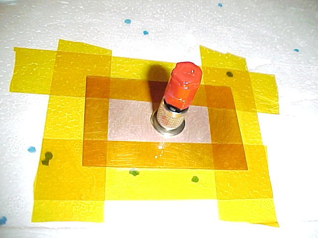
- photo of the ARM plug (54k)
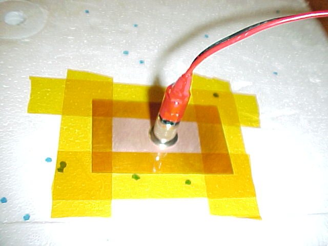
- photo of the SAFE plug (54k)
- photo of the TEST plug (43k)
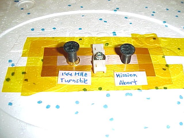
- photo of the top connectors (58k)
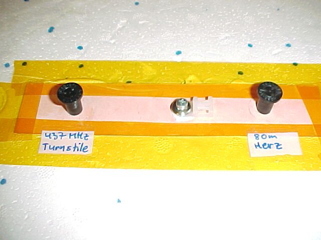
- photo of the bottom
connectors (49k)
- photo of the 1.3 GHz ATV TX output connector
(66k)
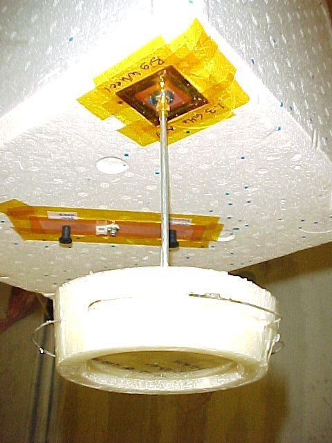
- photo of the 1.3 GHz ATV Big Wheel
flight antenna (60k)
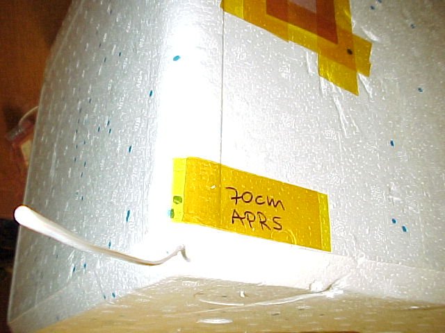
- photo of the 70 cm APRS flight antenna
(59k)
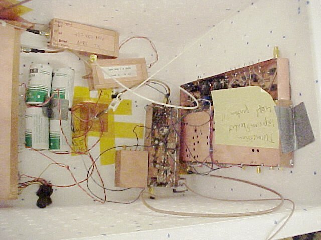
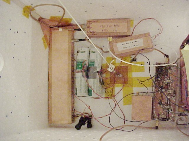
- modules and batteries need to be located within the box in a
balanced fashion: photo 1 (64k), photo 2 (62k)
- front panel interface of the remote control Command Encoder
- tässä (1k) on
OSD-prosessorin tuorein ohjaustiedosto backupiksi, eeprom-versio,
valmis ladattavaksi