
(part of ICOM IC-7610 leaflet)
ICOM has released in November 2023 a new firmware V1.40 for the IC-7610 where Digital Pre-Distortion (DPD) has been included as major new feature. Note : Unfortunately, several users have reported an issue to fix for the I/Q output on USB port, which seems 'missing in action' since the upgrade from V1.30.
This technology - already applied in high end professional transmitters - corrects nonlinear distortion at the final amplifier stage, by applying inverse distortion at the Pre-Distortion section in the FPGA unit in advance. The results are improved intermodulation distortion & 'cleaner' transmissions for complex linear modulations (like SSB, some DATA, ...) but not for CW, FM, FSK, and MSK modes. Note : as FT4 and FT8 are 'single carrier tone' modulations, there is no IMD ... and DPD has no added value/effect !
(part of ICOM IC-7610 leaflet)
DPD function provided by ICOM has been foreseen for the 'barefoot' IC-7610 and working in combination with their new 1kW PA IC-PW2, where the new function will have an even greater effect.
The purpose of this webpage is to evaluate the DPD on the IC-7610 'barefoot' and in combination with a non ICOM PA, the SPË 1K3FA, which uses as well an LDMOS device like the IC-PW2.
To carry out intermodulation distortion (IMD) measurements of a transmitter, two AF tones are injected, separated by minimum 1kHz, of exactly same level, and they should be non harmonics. For example 700 and 1900 Hz are suitable.
The idea is off course to modulate the transmitter with 2 pure (= sinusoidal) tones and to observe the waveform envelope at the output - ideally, the two tones should be present, without any other (new) spurious signals, which would result from distortions.... New signals, with the effect of 'broadening' the signal on air are undesirable, as these are 'splattering' around and causing interference to other spectrum users.
So, as a start, it is essential to have a very clean AF signal at the input of the transceiver - if the modulation AF signal(s) is/are not clean enough, they will be amplified as well and become visible at the output, and possibly misinterpreted as distortion.... Off course, it is easier and more appropriate to generate a clean suitable AF signal than attempting to clean the output readings by 'subtracting' the spuri at the input.
Now, how 'clean' should the AF two-tone signal be ?
We should stick to the general rule that, in order to measure a certain magnitude, your measuring equipment and/or test setup should be at least 10dB better that the expected value to be measured.
So, if we want to measure IMD where the distortions are in the magnitude of -30 to -40 dB, the applied audio signal should not have other signals than the two fundamental tones with a level of -50dB or better.
What are the possible 'other signals' besides the two fundamental tones ? The main unwanted signals are caused by distortions of the 2 signals themselves: if they are not pure sinusoidal, they will as well include harmonics. And if strong enough these harmonics (2f, 3f, ...) of both signals will mix together, be distorted in subsequent amplifier stages generating again some additional IMD ... resulting in severely 'garbled' output envelope, almost impossible to analyze.
So, again it must be said that it is ESSENTIAL to have clean and undistorted (= with no harmonics) AF signal at the input.
It is possible to make a relation between the harmonic distortion and signal level of this harmonic, expressed in dB vs. the fundamental. The Total Harmonic Distortion (THD) is the sum (over a certain passband) of all distortions considering harmonics. In general, the 3rd harmonic has a higher level than the 2nd, and harmonics of higher order are hereby not considered, being lower in magnitude, and outside of SSB passband.
| Harmonic signal level | Harmonic Distortion |
| -30 dB | 3.2% |
| -40 dB | 1% |
| -50 dB | 0,3% |
| -60 dB | 0,1% |
So, for our IMD measurements where we can expect a difference between fundamental and distortion products of about 60 dB, we must have AF signals with better than 70dB suppression of harmonics, or better than 0,03% distortion.
There are numerous schematic diagrams circulating on the web, from 2 transistor oscillators to more elaborated designs. There are some software's producing 'tones' as well ...
If we consider the 'hardware' approach : an oscillator is basically an amplifier, of which the output is fed back to the input, in such manner that signals are amplified in loop, in a sustainable manner. If the amplification gain is too low, oscillations will not start or stop, if set too high, signals will continue to increase till reaching a certain limit - clipping will occur - with severe distortion as result.
So, when looking for the minimal distortion, it is a matter of setting the optimal working point , and provide a kind of self regulation of amplitude in the loop to ensure oscillation will start but clipping be avoided..
I have started with a simple design from DK7IH (see https://dk7ih.de/a-simple-2-tone-generator-for-testing-the-linearity-of-ssb-transmitters/ ) , it is based on phase shift oscillators. Typically these produce up to 3% of distortion, I measured about 6% THD if we consider 2nd and 3rd harmonics.... can be used for very basic test by observing signal shape on a scope, but not for IMD measurements on a Spectrum Analyser, the output is too 'dirty', see graph below. Second harmonic is only 25dB down of fundamental, third harmonic -32dB. Same working principle for QRP-kits 'Hendricks Two Tone Generator' and many others...
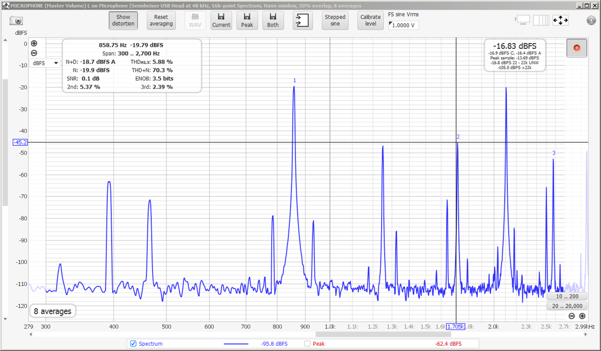
Output spectrum of 2 transistor phase shift generator - 860 & 2105 Hz (DK7IH
schematic) - click to zoom
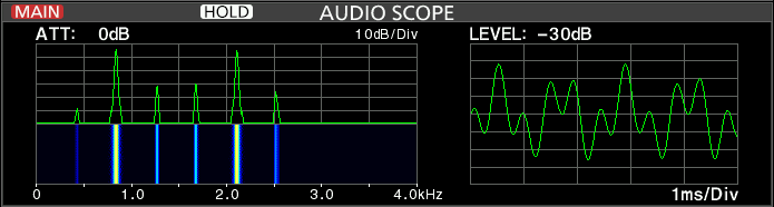
IC-7610 'Audio' screen with modulation by the same 2 transistor phase shift
generator
A better solution would be with a WIEN BRIDGE oscillator, where distortions below 0,1% can be reached, even up to 0,01% with good components. For low distortion, the internal gain must be set to a factor 3 (10dB), but this is too low to initiate the oscillations. Therefore, upon startup of circuit, the gain must be higher, and once oscillator is triggered, be reduced. This can be accomplished by introducing a negative feedback taming the gain by means of the filament of a light bulb, which behaves like a resistor with positive temperature coefficient. Exactly the principle of the audio frequency generator HP-200A, the first equipment developed and patented by Hewlett-Packard in their garage in 1939. Nevertheless, circuit design and component values need to be dimensioned with much care to obtain satisfactory results. A negative feedback can be realized as well by LDR/LED combination (vactrol) or JFET (like in the ELECRAFT '2T-GEN' generator with -55dB THD), but it seems that still best results (= lowest distortion) are to be obtained with the light bulb ...
I tested this 'light bulb' approach by assembling the generator of which schematic diagram can be downloaded here as pdf. The original diagram was borrowed from Internet (sorry I do not remember where...), I modified it for being powered from a singe 9V battery instead of two. As op-amp I used a LM358 which I had on hand, I tested with 30V/40mA and 12v/30mA midget bulbs (those where the wires are coming straight out of the glass bulb), best results were with the 12V/30mA type.
Adjusting the trimmers (10 turn type) sets the gain of the loop - this can be lowered for each frequency separately 'step by step' (wait for the lamp to re-adjust level) till the distortion doesn't drop any more- or else said, till 2nd and 3rd harmonics are no longer suppressed in a significant manner - this will be just below 0,1% THD for the low frequency (700 Hz about), where 2f and 3f are within the SSB passband (Remark : for the high frequency of abt. 1900Hz, harmonics will be outside of SSB passband) If going too far below this optimal point, THD will remain stable and eventually oscillations will stop. While this setting might not be optimal for amplitude regulation (temperature of light bulb too low, therefore Influence of room temperature ?), it is best for lowest distortion. The setpoint of the trimmers has some small influence on the frequency. The circuit will oscillate with fairly stable amplitude and frequency being powered as from 5 V about, so the 6LR61 9V battery will last long. It is certainly better to power the circuit from a dedicated battery than other sources to avoid introduction of AC-hum, ground loops etc.
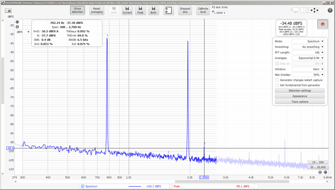
Two-tone output of Wien bridge oscillator 770 & 1930 Hz, very clean with THD <
0.1% (Click to zoom)
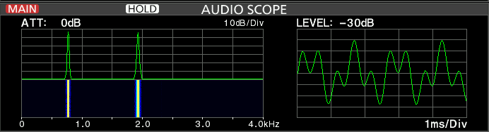
IC-7610 'Audio' screen with modulation by the same Wien bridge generator
Another circuit design, somewhat more complex and but certainly more critical regarding components selection - however still relying on a light bulb - is based on a 'state-variable oscillator', and can be downloaded here as pdf. It claims a distortion in the vicinity of -106 dB (0.0005%) - much more than we need for our IMD measurements.
Very useful information regarding hardware oscillators can be found here https://sound-au.com/articles/sinewave.htm#s9 and http://www.i6dvx.it/en/lavori-in-corso/generatore-due-toni.html (unfortunately gone SK in 2017)
If we go for 'software' approach, there are some little utilities around producing 'tones' with more or less distortion, but the very best I can recommend is REW (Room Equalization Wizard - see https://www.roomeqwizard.com/ )
This software (free of charge) is intended for audiophiles who want to finetune the frequency response of their HiFi system in function of the room acoustics - not really something to do with IMD measurements, but it offers a very good AF generator and spectrum analyzer, which directly reads out in % distortion, over a selectable passband (limited to e.g. 300 ... 2700 Hz). 'Out of the box', without any calibration, I could measure single tones generated by REW as with 0,0046% ( > 80dB) THD, simply by a loopback cable between 'LINE OUT' and 'LINE IN' of the soundcard of my PC.
Two tones (700 and 1900 Hz) produced as well nice and clean spectrum, where spurious were better than 80dB below fundamentals - exactly what we need for IMD measurements to check DPD ! Click on the screenshots below to zoom.
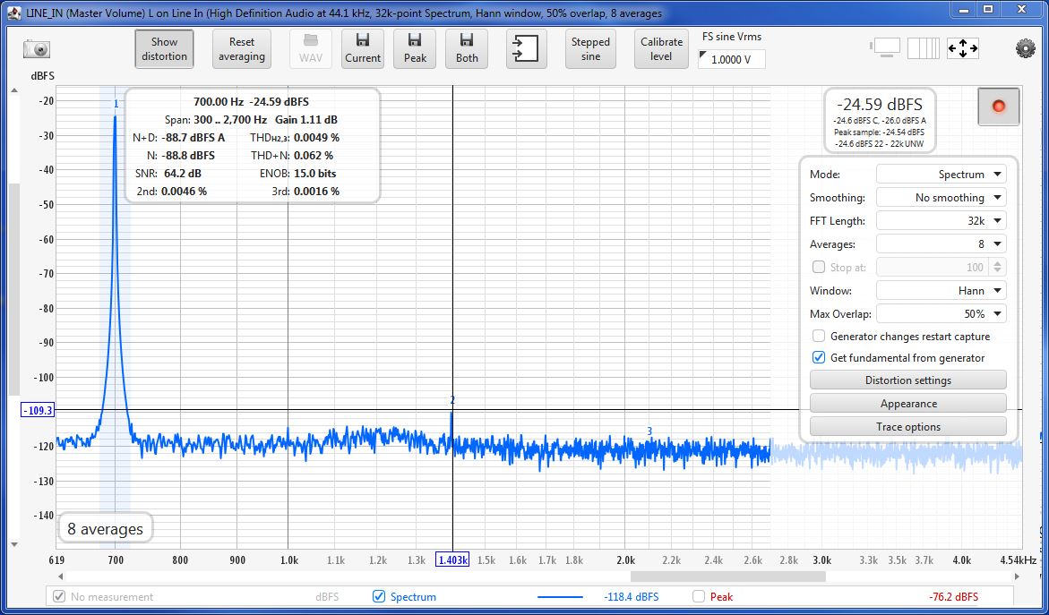
Single tone 700 Hz, first harmonic 89 dB down of fundamental, THD 0,0046%
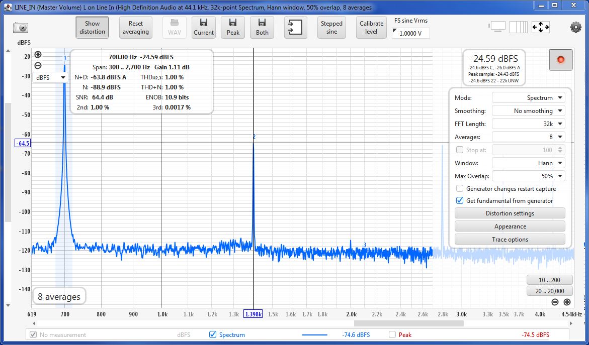
Singe tone 700 Hz, with voluntary 1% THD introduced, first harmonic 40 dB down
of fundamental
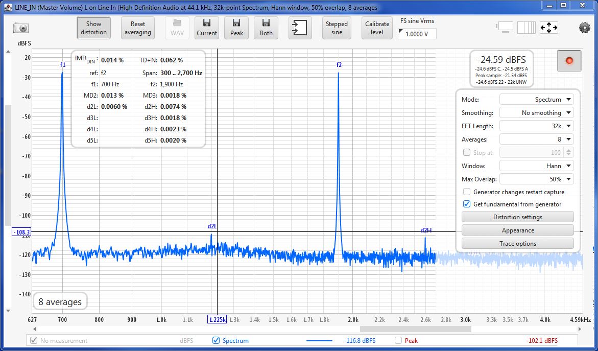
Two-tone 700 & 1900 Hz, mixing products D2L and D2H visible at 83 dB down of
fundamentals, THD 0,014%
The tests were performed under following conditions :
If in doubt about 'power per tone', 'average/mean power' and 'Peak Envelope Power (PEP) see pdf document and pdf document.
Yellow trace with DPD=OFF, blue trace with DPD=ON. Third order IMD
29.3 dB down
of PEP power.
Blue trace off-setted by -10dB to avoid superimposition with yellow
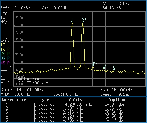
IMD with DPD=ON. 3rd order products -58,3 dB down + 6 dB =
-64.3 down of PEP power
(according to
ITU Rec. ITU-R SM.326-7) - congratulations to ICOM engineers !
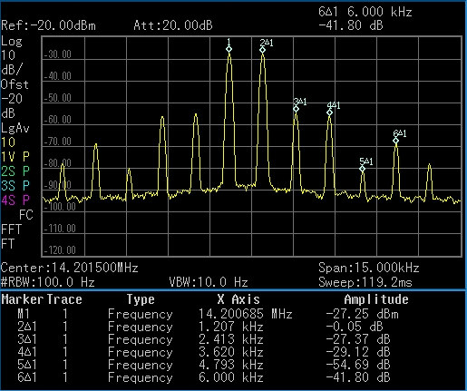
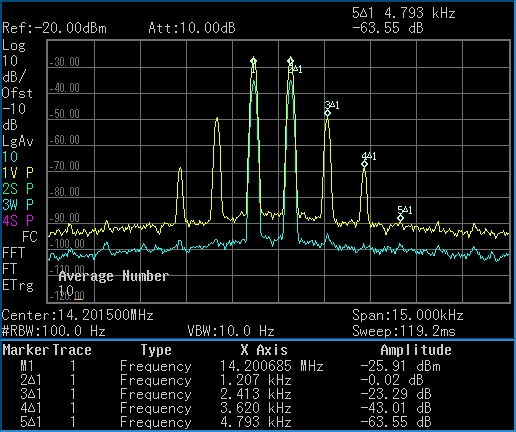
IMD products on SPE output, 1kW mean power out (MID power setting), with DPD=OFF
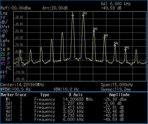
IMD products on SPE output, 1kW mean power (MID power setting), with DPD=ON
Effect of DPD is minimal, even 5 dB
worse for third order (marker 3)
For fourth order (marker 4) 3 dB enhancement.
Other orders are better than -40 dB down and not really relevant anymore.

IMD on SPE output 1kW mean power (MID power), yellow trace is DPD=OFF, blue trace is DPD=ON
Blue trace off-setted by -10dB to avoid superimposition with yellow
I