ARDUINO control of 1.2 / 1.8 kW Solid State LDMOS PA
Solid State VHF PA's are currently commercially
offered on the market by many manufacturers (BEKO, ...) but are quite
expensive (2.500 - 4.000 EUR), so it is certainly worth to consider a
'homebrew' alternative.
This project describes an ARDUINO based control of a
Solid State PA (
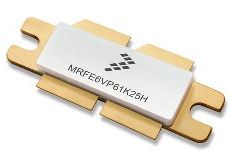
concept F1JRD ). Like most of recent SSPA's, this PA is using one
LDMOS transistor (Freescale MRFE6VP61K25H able to produce 1.250W RF
for only 2.5W input. -
see excellent application note of Freescale here) which is quite rugged
(advertised to withstand a SWR of 1:65) but nevertheless needs to be
carefully monitored as it is running under 50v, drawing up to 35A and
this device costs about 250 EUR ! And yes, I have already sent
one TWO to "semiconductor's heaven" so had to design
something to protect it in the most efficient manner...
Recently, NXP introduced two new 'enhanced' versions of
this LDMOS : a 1.5 kW (see
datasheet) and even a 1.8kW (see
datasheet) type are available !
With these higher power, it is imperative:
-
to solder the LDMOS to the copper heatspreader
(see W6PQL instructions, using ordinary solder wire ... but you need to
heat up till 220-230°C, beyond NXP's 'survival' specs!). I however used
MECHANIC XGS40 Special Liquid SolderPaste 158°C , which is developed
for delicate SMD components, melts already at 200°C and offers excellent
wetting (ensuring a perfect thermal joint). This operation can be
performed perfectly and in complete confidence in a household oven. You
can find the stuff on Ebay ...
-
to use more rugged ATC capacitors than these
originally specified, use ATC 100B 'Extended Voltage'
series - these can handle about the double of current as well for
small values (< 20 pF about). See
ATC series
100B catalog here
-
to provide a thermally well compensated bias voltage
- the 1.8kW version requires @ 50V about -2,6 mV/°C compensation.
Calculate if your circuit (with a NTC?) for Vgs of about 3V is compliant
from 20-50°C !
See interesting article here for a simple solution... not 100%
correct as a NTC R/T curve is is not linear but logarithmic, unless you
consider 20 - 50°C range ...

Pallet fitted with 1k8
LDMOS
In my most recent PA, I used the 1.8 kW device (which
is somewhat 'lazier' than the 1.2kW version ...) @ 55V for SSB
(limiting output to 1.2 kW) and 48V for Digital modes (limiting
output to 800w), this provides enough safety margin for any 'mishap'. For
digital modes, in order to limit the heat dissipation, it is essential to
LOWER the power supply voltage and drive the device into compression - this
will ensure optimal efficiency ! (Thx Lionel F1JRD for the tip). Commercial
equipment (like produced by SPE, using same NXP LDMOS) as well adapt their
power supply voltage according to LOW / MID / HIGH power setting. As the
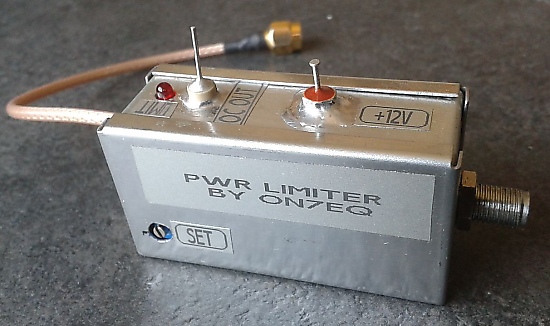
LMDOS is driven well into compression, it is advisable as precaution
to use a circuit limiting the input power fed to the LDMOS to 7W -
see my simple but
effective solution here, with a PIN diode UM9401 salvaged from a
defective TRX.
In this project, ARDUINO will take care of following
vital functions :
-
Check of all critical parameters upon startup : 3
voltages, idle current, temperature, NTC circuit, perform a fan
test, RX/TX status, ..... (performing a system seltest)
-
When operating :
-
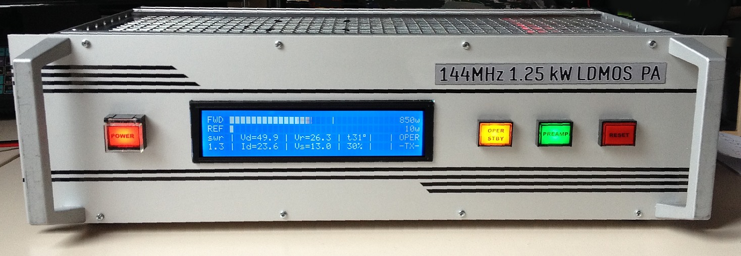
Display of forward and reflected power, on a bar
graph scale (with PEP peak hold indicator) & numeric power (PEP)
-
Calculation & display of SWR
-
Display all critical supply voltages : +
50v DC LDMOS power, +28v relay (generated via step-up circuit),
+13.8v circuits power
-
Display +50v current consumption (with peak hold)
-
Control of +50v supply line
-
Display of heat sink temperature & control of fan
(PWM), % fan RPM indication
-
Display of PREAMP & OPER / STBY status
-
Check if PA is operated in SSB or DIGITAL mode
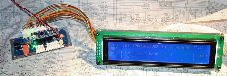
The display is a 4 x 40 high contrast LCD display,
with efficient LED backlight (only 2 white LEDS, drawing 20 mA total).
As this type of display has 2 Hitachi
HD44780 drivers on board, a specific
library must be used (see below)
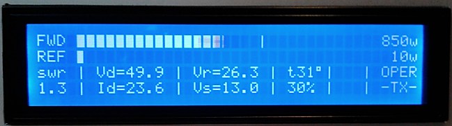
FWD bar graph full scale is 1.250W, REFL full scale is 125W
-
Following parameters are constantly (perhaps 100x per
second) monitored - if any fault is detected, the amplifier is instantly
put in STBY mode and the 50v supply is cut off :
-
Over- and under voltage of 50v, 28v, 13.8 v
-
Excessive idle current of +50v in RX mode
-
Excessive current +50v in TX mode (''electronic
fuse'')
-
Excessive output power
-
Excessive SWR
-
Excessive temperature
-
Correct status when going into OPER mode (e.g.
going into OPER is only possible in RX mode)
If the SSPA goes into protection, the fault condition
will be displayed and the RESET push button flashing + buzzer sounding.
After depressing the RESET button, the SSPA will first initiate a self
test to ensure that the error has effectively been cleared.
The SSPA has a 'test' mode for playing around with no
+50v supplied - so nothing can go wrong ... To enter this TEST mode,
power up while the RESET button is depressed - it will then run in 'test'
mode and ignore any 50v related errors.
ARDUINO will as well take care of controlling the cooling
fans. The SSP pallet is mounted on a huge cooling 'brick',
ventilated by 2 compact & powerful - thus very noisy - fans.
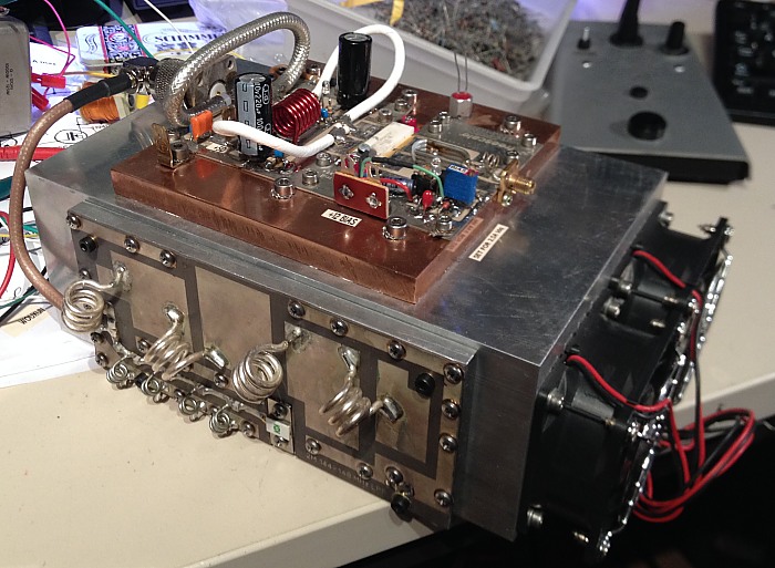
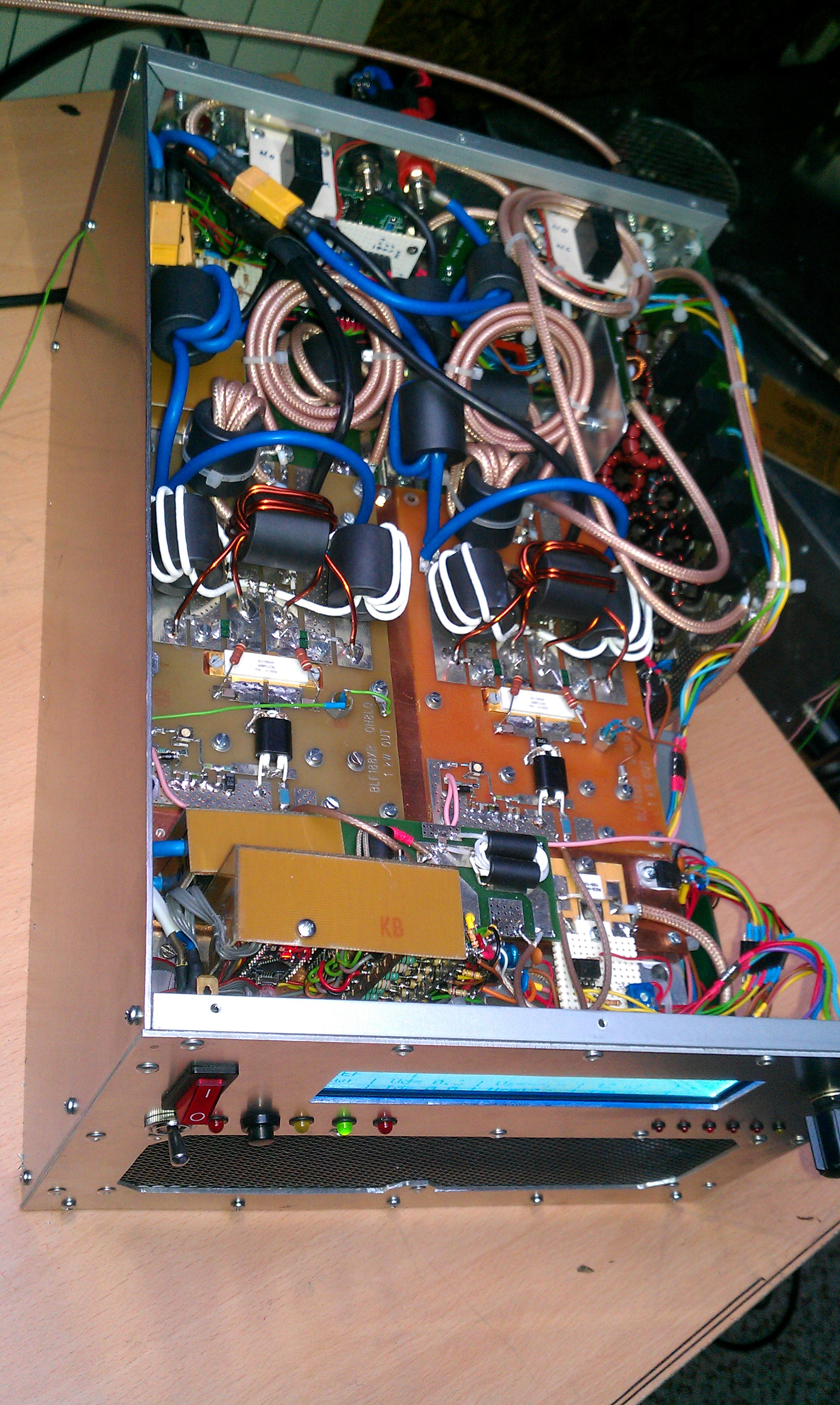
The RF pallet on the
cooling brick, complete with output filter.
Running at full speed, it is like a helicopter taking off
in the shack ! So not very comfortable to implement an 'all or
nothing' control of fans... Instead, ARDUINO will monitor the
temperature and progressively (PID - Proportional - Integral - Differential)
regulate their RPM by PWM control. The result is that the pallet
temperature will never exceed 50°C and fan speed is adapted smoothly as
required.. There is as well a detection of 'EME' modes built-in : if the
power is constant (like for JT65A) above a certain level, ARDUINO will have
the fans running at 100% in a pro-active manner.
I used the 'Ultimate PA control board' of Jim W6PQL ( see
http://www.w6pql.com/amplifier_control_board.htm ) for it's excellent
sequencer (and ALC control), it as well monitors the SWR and temperature as
redundant protection. In turn, if any fault condition is detected, ARDUINO
will signal this to the PA control board (which as a 'force RX' input) which
will immediately revert the SSPA into RX mode in a graceful manner.

Compact PA in 19" chassis 3U high - including the low-pass filter & DB6NT
HEMT preamp - the power supply is external - Click to zoom.
See the PA sketch in action here (YouTube) :
https://www.youtube.com/watch?v=0fD5piBHD0o
https://www.youtube.com/watch?v=7sXOMGHFyPU
https://www.youtube.com/watch?v=47pa17hgofY
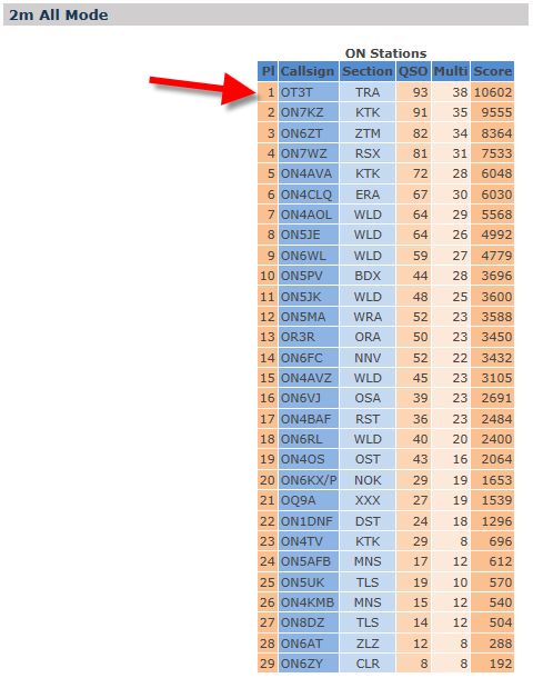
Stress-testing the new PA in the UBA Spring contest
- 2m - March 2015 : 1st place !
Amplifier used for operating MS from Andorra (C3) -
Perseids 2016
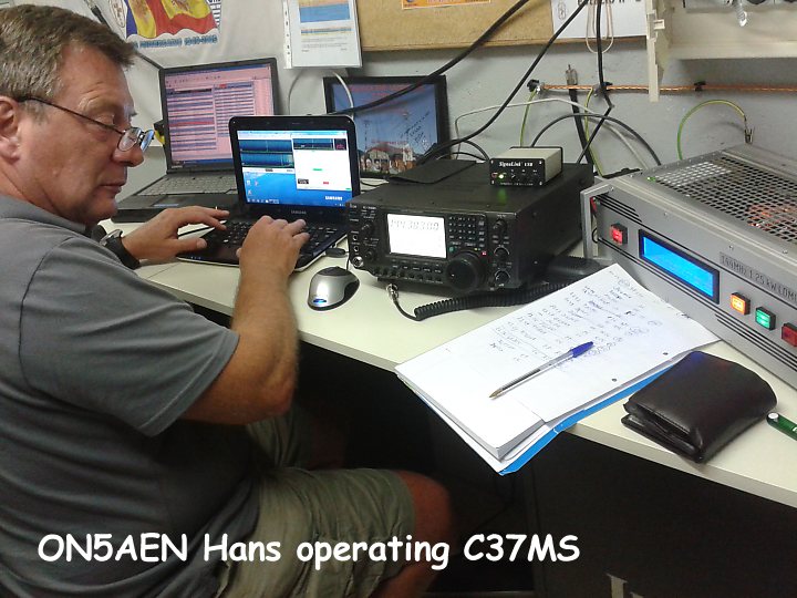
Running 700 - 800 W in Meteor
scatter mode during more than 100 hours !
NOTES :
-
This project is definitely not for beginners !
You must be able to adapt yourself the sketch according to your
particular in/outputs, sensors, voltages, etc ... The sketch is well
commented, and sorry if I cannot support you by re-coding the sketch for
you. I have even received requests for instructions "how to upload
the sketch into the ARDUINO board". If you are not (yet !) familiar
with ARDUINO, take some time to first learn the basics - you will
be amazed about your progress !
-
Needless to say, it is essential that all ARDUINO
inputs are properly RF decoupled or erratic readings will result from
stray RF pickup I have seen reports on some web sites that my
sketches for other project (the power/swr meter) are a 'disaster'
and not functioning, well this is purely due to the fact that input
lines were not properly decoupled by project builders! All critical
input must be fed trough 2x feedthrough capacitors and a RF choke put in
line in between, while ARDUINO must be housed in a small RF-tight
enclosure. The output lines (including LCD drive) are not as
critical.
-
Same is true for the ATTOPILOT high side current
probe (see
specs here) I used to measure +50v supply current to PA. The INA169
inputs seem to be very sensitive to RF !
-
The LiquidCrystal440 library and code for the
bargraph display were taken from public domain on the internet, many
thanks for who posted this !
-
Here is
the 4x 40 LCD display datasheet. The backlight resistors should be
dimensioned to provide 30mA (50mA max!) @ 5v. Contrast and
intensity are excellent !
-
I used an ARDUINO nano board - very compact, still
flashable by USB, and it offers one port more than UNO version. The USB
connection of the nano board was extended to the rear of the PA chassis,
so that ARDUINO can be flashed without opening the 19" cabinet.
-
To control the 50v line (electronic power switch &
fuse), I recommend using a pair of SUP90P06-09L P-Channel 60 V MOSFETS
put in parallel, providing each a Drain-Source On-State Resistance (RDS)
of only 0.0074 Ohm ! I have tested with other types, but too much
voltage drop. See spec sheet of SUP90P06-09L P-here
(PDF 100 kB)
-
Sorry I cannot provide any decent schematic diagram
of modules except
this rough interconnection sketch .... and RX3DR
Alexander was so kind to
draw it more properly here - thx !
-
I have adapted the initial sketch (for 1.2kW version)
for the 1.8kW version, see below - dated 2018. This version checks if PA
is operating in SSB or DIGITAL mode and triggers error message if supply
voltage is too high in DIGITAL mode.
DOWNLOADS:
It was compiled with IDE version 0022.-
IMPORTANT : please use the same or you will get errors when compiling
! You still can
download previous versions from ARDUINO website IDE version 0022 runs
fine on my Win7PRO 64 and 32bit machine and compiles with no errors.
As from IDE V1.00 many functions & libraries were
redefined... have attempted to transcode old to new, but encountered
so many errors that I finally gave up. Even after including 'WProgram.h' and
'wiring.h', a dozen of new errors appeared, and even if these were solved,
no guarantee that it will work on the board. I anybody succeeded to
recompile in IDE version 1 or more recent please advise so this can be
shared !
Update June 2021 : Alex HB9DRI has been so kind to
inform that he succeeded to compile under IDE V1.8.3 (= the last one before
V2 ... where again several instructions changed ... ) . He uses the sketch
since 2 years for his 1kW 70cm SSPA without any problems. Apparently, the
problem is in the library for the LCD which I originally used - instead, use
this one :
https://github.com/jurs/liquidcrystal440
or
download it from my site. Then :
-
Save the library (unzipped !) in the IDE
libraries folder, and rename the folder to "LiquidCrystal".
-
Using IDE 1.8.3, import the sketch (change file
extension to "ino" instead of older "pde" naming)
-
Modify in the sketch the include
LiquidCrystal440.h to
LiquidCrystal.h
-
Compile and enjoy !
Many thanks for info Alex !
(see other ARDUINO stuff under
'PROJECTS' page)
Branko S52V realized a nice HF PA 1.5 kW
with 2 pallets bridged running each a BFL-188 XR, using my sketch as base -
click on pictures to zoom in !
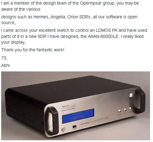
Parts of the sketch are used as well in the
ANAN-8000LE 200w SDR HF transceiver - see excerpt of the
instruction manual
here
The sketch of ANAN can be
downloaded here.
(Have tried to compile it with IDE 1.8.12 but gives errors)
Marc F6ITU has with a group of OM's used the sketch in a SDR transceiver
project, and developed a series of PCB's ("Mentor" and "Télémaque") to
nicely integrate everything (instead of working with VERO perf boards like I
did).
Mentor prototype PCB
Information can be found on :
This is the sketch version for 1.2 k LDMOS (see
below for 1.8 k LDMOS version)
/*
////////////////////////////////////////////////////////////////////////
/// ///
/// SOLID STATE POWER AMPLIFIER READOUT & PROTECTION CIRCUIT ///
/// ///
////////////////////////////////////////////////////////////////////////
By ON7EQ 02/2015
Compiled with IDE 0.22 for ARDUINO NANO board
Connected with W6PQL SSPA controller
ARDUINO NANO CONNECTIONS
________________________
PIN DESCRIPTION TO PIN
ANALOG
A0 Forward voltage directional coupler Dir coupler FWD
A1 Reflected voltage directional coupler Dir coupler REFL
A2 NTC 10k NTC (10k to +5v)
A3 50v supply - voltage ATTOPILOT Voltage
A4 50v supply - current ATTOPILOT Current
A5 26v supply - Voltage
A6 13.8v supply - voltage
A7 PTT - read status
DIGITAL I/O
0 I Serial RX & input recover switch (0 = recover)
1 I Serial TX & Input PREAMP status (0 = preamp ON)
2 I "Operate" status read Logic HI = operate
3 O +50v Supply control Output, logic HI = ON
4 O Buzzer Output, Logic HI = sounding
5 O FAN Control (PWM port) Output, Logic HI = 'ON' pulse to Mosfet Gate
6 O LCD : DB7 LCD 01
7 O LCD : DB6 LCD 02
8 O LCD : DB5 LCD 03
9 O LCD : DB4 LCD 04
10 O LCD : En2 LCD 15
11 O LCD : En1 LCD 09
12 O LCD : RS LCD 11
13 O FAULT (PTT BLOCK W6PQL) Logic HI = Kill PTT via open collector output
===================================================================
NTC Thermistor Schematic
===================================================================
(+5v ) ---- (10k-Resistor) -------|------- (Thermistor) ---- (GND)
|
Analog Pin 'IN_NTC'
*/
// include 4x40 LED driver
#include <LiquidCrystal440.h>
// include math functions
#include "math.h"
uint8_t nRows = 4; //number of rows on LCD
uint8_t nColumns =40; //number of columns
// Modify the pin number below to meet your board
//Analog pins
#define IN_FWD A0 // analog input for left channel
#define IN_REFL A1 // analog input for right channel
#define IN_NTC A2 // analog input for right channel
#define IN_50vv A3 // analog input for 50v voltage
#define IN_50vI A4 // analog input for 50v current
#define IN_26v A5 // analog input for 26v voltage
#define IN_12v A6 // analog input for 12v voltage
#define IN_PTT A7 // analog input for PTT detect (0 = keyed)
// Digital pins
#define IN_reset 0 // input for recover/SELFTEST switch detect - momentary pulling to GND (0 = recover/SELFTEST)
#define IN_PREAMP 1 // input for Preamp detect (1 = ON)
#define IN_OPERATE 2 // input for operate detect (1 = OPERATE)
#define supply_50v 3 // output for 50v supply control (1 = 50v ON)
#define Buzzer 4 // output for Buzzer control (1 = ON)
#define FANcontrol 5 // output for FAN control (PWM !)
#define PTT_block 13// output for PTT block control (no alarm = 0, FAULT = 1...n)
// Other minor configurable value
#define T_REFRESH1 50 // msec bargraph refresh rate
#define T_REFRESH2 500 // msec refresh rate other variables
#define T_PEAKHOLD 600 // msec peak hold time before return
#define T_pepHOLD 600 // msec pep hold time before return
#define R1 (10) // from GND to IN_26v, express in 100R (12 = 1200 Ohm)
#define R2 (82) // from + power supply to IN_26v, express in 100R (47 = 4700 Ohm)
#define R3 (12) // from GND to IN_12v, express in 100R (12 = 1200 Ohm)
#define R4 (47) // from + power supply to IN_12v, express in 100R (47 = 4700 Ohm)
// FAN speeds (0 ... 255) PWM driven
#define fan_vy_slow (20) // Very slow, idle speed
#define fan_slow (30) // Slow
#define fan_med_lo (40) // Medium speeds, low
#define fan_med_hi (50) // Medium Hi, start of PID regulation till 255 = max !
// Calibration factors
int calibrP = 540; // Assume 3.3v = 1.000w in 50R. CalibrP = (3.3 / 5.0 x 1024 + Vdiode)x(3.3 / 5.0 x 1024 + Vdiode) / 1000w
int Vdiode = 60; // if we assume FWD voltage diode = 0,3v : Vdiode = 0,3 v / 5.0 v x 1024
// local variable
byte fill[6]={ 0x20,0x00,0x01,0x02,0x03,0xFF }; // character used to fill (0=empty 5=full)
byte peak[7]={ 0x20,0x00,0x04,0x05,0x06,0x07,0x20 }; // character used to peak indicator
int lmax[5]; // level max memory
int dly[5]; // delay & speed for peak return
long lastT1=0; // update display timer1
long lastT2=0; // update display timer2
long lastTpep = 0; // update PEP display
long lastTempTime = 0; // update last temp readout for fan control
long LastTXtime = 0; // timestamp when last transmission ended (for FAN control)
long HiPowerTime = 0; // timestamp Hig Power - for EME conditions
long HiAmp50Time = 0; // timestamp high current value on 50v power supply
long LoVolt50Time = 0; // timestamp low voltage value on 50v power supply
int anF = 0; // analog read forward power
int anR = 0; // analog read reflected power
int volt_50 = 0; // 50v volt supply - voltage (in 0,1 volt)
int amp_50 = 0; // 50v volt supply - current (in 0,1 Amp)
int amp_50_max = 0; // 50v volt supply - max current (in 0,1 Amp)
int volt_26 = 0; // 26v volt supply - voltage (in 0,1 volt)
int volt_12 = 0; // 13,8 v volt supply - voltage (in 0,1 volt)
int temp = 0; // temperature (in 1 °C)
int lasttemp = 0; // last temperature for fan control
byte PTT = 0; // 0 = RX, 1 = TX
byte wasPTT = 0; // former RX/TX status byte : if 1 = was in TX mode
byte TestMode = 0; // 0 = normal mode, 1 = TestMode (PA will 'operate' with no +50v). Testmode is
// initiated by depressing 'RESET4 button upon startup of SSPA
int Operate = 0; // When operate = 0 , PA in stby mode
int FAN = (0); // Fan control (PWM) - 255 = full speed
byte HiTemp = (0); // Temperature passing above PID start temp
byte FAULT = 0; // when FAULT = 0 : NO FAULT
// when FAULT = 1 : Overcurrent
// when FAULT = 2 : voltage error 50v
// when FAULT = 3 : voltage error 26v
// when FAULT = 4 : voltage error 12v
// when FAULT = 5 : power out error
// when FAULT = 6 : SWR error
// when FAULT = 7 : NTC sensor read error
// when FAULT = 8 : Temperature error
// when FAULT = 9 : 50v idle current error
// when FAULT = 10: W6PQL control PCB SWR exceed fault
byte FirstLoop = (1); // First loop detect
byte SelfTest = (1); // 1 to force selftest
byte HiAmp50 = (0); // Flag to detect long lasting current peaks on 50v supply
byte LoVolt50 = (0); // Flag to detect long lasting voltage dip on 50v supply
byte EMEmode = (0); // 0 = normal, 1 = EME conditions (no SSB but CW/JT65)
unsigned long pow_fwd = 0; // power forward (watts)
unsigned long pow_ref = 0; // power reflected (watts)
unsigned int pow_fwd_max = 0; // power forward max (for peak hold)
unsigned int pow_ref_max = 0; // power reflected max (for peak hold)
float SWR = 0; // SWR
float Pratio = 0; // Power ratio P forward / P refl
int SWRDis = 0; // power calculation for showing in display
LiquidCrystal lcd(12,255,11,10,9,8,7,6); // (RS,RW,En1,En2,D4,D5,D6,D7) 255 if RW is connected to GND and not controlled by the interface.
//=====for a 4x40 LCD with 2 HD44780 type chips and 18 pin interface in 2 rows of 9;
// LCD Nano Signal
// 18 Gnd Backlight white on blue 4x LED draws 40 mAmps
// 17 +5V Backligt + through external resistor 15 Ohm.
// 16 NC not used
// 15 10 En2 -- enable the 2nd HD44780 chip which controls the bottom 2 rows of the display
// 14 +5V supply logic
// 13 Gnd logic
// 12 Wiper of contrast resistor (22k between +5v and Gnd)
// 11 12 RS
// 10 Connect to Gnd
// 9 11 En1 -- enable the 1st HD44780 which controls the top 2 rows
// 5-8 Data 0-3: not used in 4 bit modes
// 1-4 09-06 Data 4-7: LCD DB7 to ARDUINO 06, DB6 to 07, DB5 to 08, DB4 to 09
/////////////////// DRAW BAR //////////////////////////
void bar ( int row,int lev )
{
lcd.setCursor( 3,row );
lcd.write( row ? ' ' : ' ' );
for( int i=1 ; i<30 ; i++ )
{
int f=constrain( lev -i*5,0,5 ); // Level instant
int p=constrain( lmax[row]-i*5,0,6 ); // Level maximum (=peak)
if( f )
lcd.write( fill[ f ] );
else
lcd.write( peak[ p ] );
}
if( lev>lmax[row] )
{
lmax[row] = lev;
dly[row] = -(T_PEAKHOLD)/T_REFRESH1; // Starting delay value. Negative=peak don't move
}
else
{
if( dly[row]>0 )
lmax[row] -= dly[row];
if( lmax[row]<0 )
lmax[row]=0;
else
dly[row]++;
}
}
byte block[8][8]=
{
{ 0x10,0x10,0x10,0x10,0x10,0x10,0x10,0x10 }, // define character for fill the bar
{ 0x18,0x18,0x18,0x18,0x18,0x18,0x18,0x18 },
{ 0x1C,0x1C,0x1C,0x1C,0x1C,0x1C,0x1C,0x1C },
{ 0x1E,0x1E,0x1E,0x1E,0x1E,0x1E,0x1E,0x1E },
{ 0x08,0x08,0x08,0x08,0x08,0x08,0x08,0x08 }, // define character for peak level
{ 0x04,0x04,0x04,0x04,0x04,0x04,0x04,0x04 },
{ 0x02,0x02,0x02,0x02,0x02,0x02,0x02,0x02 },
{ 0x01,0x01,0x01,0x01,0x01,0x01,0x01,0x01 },
};
///////////////// PRINT TEMPLATE ///////////////////
void printtemplate () {
lcd.setCursor( 0,0 );
lcd.print( "FWD 0w");
lcd.setCursor( 0,1 );
lcd.print( "REF 0w");
lcd.setCursor( 6,2 );
lcd.print( "Vd=--.-");
lcd.setCursor( 6,3 );
lcd.print( "Id=--.-");
lcd.setCursor( 16,2 );
lcd.print( "Vr=--.-");
lcd.setCursor( 16,3 );
lcd.print( "Vs=--.-");
lcd.setCursor( 26,2 );
lcd.print( "t--");
lcd.print((char)223); //degree symbol
//lcd.print((char)165);
lcd.setCursor( 0,2 );
lcd.print( "swr");
lcd.setCursor( 0,3 );
lcd.print( "-.-");
/* PREAMP
lcd.setCursor( 31,2 );
lcd.print( "PRE");
lcd.setCursor( 31,3 );
lcd.print( "AMP");
*/
lcd.setCursor( 36,2 );
lcd.print( "stby");
lcd.setCursor( 4,2 );
lcd.write( peak[3] );
lcd.setCursor( 4,3 );
lcd.write( peak[3] );
lcd.setCursor( 14,2 );
lcd.write( peak[3] );
lcd.setCursor( 14,3 );
lcd.write( peak[3] );
lcd.setCursor( 24,2 );
lcd.write( peak[3] );
lcd.setCursor( 24,3 );
lcd.write( peak[3] );
lcd.setCursor( 30,2 );
lcd.write( peak[3] );
lcd.setCursor( 30,3 );
lcd.write( peak[3] );
lcd.setCursor( 34,2 );
lcd.write( peak[3] );
lcd.setCursor( 34,3 );
lcd.write( peak[3] );
}
/////////// This function will calculate temperature from 10k NTC readout /////////////
double Thermister(int RawADC) {
double Temp;
Temp = log(((10240000/RawADC) - 10000));
Temp = 1 / (0.001129148 + (0.000234125 + (0.0000000876741 * Temp * Temp ))* Temp );
Temp = Temp - 273.15; // Convert Kelvin to Celcius
// Temp = (Temp * 9.0)/ 5.0 + 32.0; // Convert Celcius to Fahrenheit
return Temp;
}
////////////////////////////////////////////////////////////////
/////////////////////////// SETUP //////////////////////
////////////////////////////////////////////////////////////////
void setup() {
/// Prepare I/O pins
pinMode(IN_PREAMP, INPUT);
pinMode(IN_OPERATE, INPUT);
pinMode(IN_reset, INPUT);
digitalWrite(supply_50v, LOW); // We do not allow +50v yet
pinMode(supply_50v, OUTPUT);
digitalWrite(Buzzer,0);
pinMode(Buzzer, OUTPUT);
analogWrite(FANcontrol,FAN);
digitalWrite(PTT_block,HIGH); // we force RX mode till all is OK !
pinMode(PTT_block, OUTPUT);
lcd.begin(nColumns,nRows);
for( int i=0 ; i<8 ; i++ )
lcd.createChar( i,block[i] );
lcd.clear();
lcd.setCursor(5,0 );
lcd.print ("1 . 2 5 k W V H F S S P A ");
lcd.setCursor(5,2 );
lcd.print (" by O N 7 E Q ");
lcd.setCursor(5,3 );
lcd.print (" 05/2015 - V1.08 ");
delay (2000);
lcd.clear();
delay (500);
printtemplate();
lastT2 = millis(); // set T2 display refresh
}
///////////////////////////////////////////////////////////
/////////////////////////// LOOP //////////////////////////
///////////////////////////////////////////////////////////
void loop() {
// Check if TESTMODE required. Testmode is initiated by depressing the RESET button upon powering up.
// In testmode, no 50v supply is applied to PA pallet, and no 50v is required to go into 'OPERATE' and 'TX' mode
// exiting TESTMODE is only possible by powering up again SSPA
if (((digitalRead(IN_reset) == LOW) or (TestMode == 1))and (FirstLoop == 1) ) {
TestMode = 1;
lcd.setCursor(10,0 );
lcd.print ("T E S T M O D E !");
lcd.setCursor( 7,1 );
lcd.print ("(N O + 5 0 v T O P A)");
digitalWrite(Buzzer,HIGH);
delay (200);
digitalWrite(Buzzer,LOW);
lcd.setCursor(10,0 );
lcd.print (" ");
lcd.setCursor( 7,1 );
lcd.print (" ");
delay (200);
digitalWrite(Buzzer,HIGH);
lcd.setCursor(10,0 );
lcd.print ("T E S T M O D E !");
lcd.setCursor( 7,1 );
lcd.print ("(N O + 5 0 v T O P A)");
delay (200);
digitalWrite(Buzzer,LOW);
lcd.setCursor(10,0 );
lcd.print (" ");
lcd.setCursor( 7,1 );
lcd.print (" ");
delay (200);
digitalWrite(Buzzer,HIGH);
lcd.setCursor(10,0 );
lcd.print ("T E S T M O D E !");
lcd.setCursor( 7,1 );
lcd.print ("(N O + 5 0 v T O P A)");
delay (200);
digitalWrite(Buzzer,LOW);
delay (500);
printtemplate();
}
// update OPERATE / STBY mode
if (digitalRead(IN_OPERATE) == HIGH) Operate = 1;
else Operate = 0;
// update PTT status
if (analogRead(IN_PTT) < 512) PTT = 1;
else PTT = 0;
// Check if no PTT & operate mode at startup of our PA
if ((Operate == 1) and (FirstLoop == 1) and (PTT == 1)) {
digitalWrite(Buzzer,HIGH);
lcd.setCursor(5,0 );
lcd.print ("SET TRANSCEIVER IN RX PLEASE !");
delay (500);
digitalWrite(Buzzer,LOW);
printtemplate();
delay (500);
loop();
}
// perform every loop some measurement we need for critical faults detection
// __________
// Current 50v
amp_50 = map (analogRead(IN_50vI),0,1023,0,1680); //90 Amp ATTOPILOT board - convert to 0,1 A
if (amp_50 < 31) amp_50 = amp_50 + (amp_50/4) ; // Arduino not linear at very low voltages ?
if (amp_50 < 51) amp_50 = amp_50 + (amp_50/7) ;
if (amp_50 < 101) amp_50 = amp_50 + (amp_50/10) ;
if (amp_50 < 150) amp_50 = amp_50 + (amp_50/20) ;
if (amp_50 > amp_50_max) amp_50_max = amp_50; // measure peak current every T1 to display max every T2
//Detect current peak (instantaneous, 'never exceed' value) :
if (amp_50 >= 400) { // Critical overcurrent ! peak with more than 40A !
FAULT = 1;
fault(); // Jump to FAULT handling
}
//Detect current 'long lasting' peak (overdrive of PA - protect LDMOS) :
if (amp_50 >= 350) { // more than 35A
if (HiAmp50 == 0) HiAmp50Time = millis(); // timestamp reading
HiAmp50 = 1;
}
else (HiAmp50 = 0);
if ((HiAmp50 == 1) and ((millis() - HiAmp50Time) > 30)) { // we have a peak lasting more than 30 ms
HiAmp50 = 0;
FAULT = 1;
fault(); // Jump to FAULT handling
}
// Voltage 50v
volt_50 = map (analogRead(IN_50vv),0,1023,0,788); //90 Amp ATTOPILOT board - convert to 0,1 V
if ((volt_50 >= 550) ){ // Overvoltage, always alarm !
FAULT = 2;
fault(); // Jump to FAULT handling
}
if ((volt_50 <= 430) and (Operate == 1) and (TestMode == 0) and (PTT == 0) ){ // Undervoltage while in operate mode, in RX ! Fault in pallet ?
FAULT = 2;
fault(); // Jump to FAULT handling
}
// detect long lasting voltage dip
if ((volt_50 <= 450) and (Operate == 1) and (TestMode == 0) and (PTT == 1) ){ // Undervoltage while in TX mode
if (LoVolt50 == 0) LoVolt50Time = millis ();
LoVolt50 = (1);
}
else (LoVolt50 = 0);
if ((LoVolt50 == 1) and ((millis() - LoVolt50Time) > 100)) { // we have a dip >100 ms !
LoVolt50 = 0;
FAULT = 2;
fault(); // Jump to FAULT handling
}
// Voltage 26v. Make sure RF relays can be energized !
volt_26 = map(analogRead(IN_26v), 0,1023,0,(50*(R2+R1)/R1)) + 1;
if(volt_26 == 1) volt_26 = 0; // 'zero volt' rounding orreection
if ((volt_26 >= 300) or (volt_26 <= 230) ){ // Under or overvoltage, always alarm !
FAULT = 3;
fault(); // Jump to FAULT handling
}
// Voltage 12v.
volt_12 = map(analogRead(IN_12v), 0,1023,0,(50*(R4+R3)/R3));
if ((volt_12 >= 150) or (volt_12 <= 110) ){ // Under or overvoltage, always alarm !
FAULT = 4;
fault(); // Jump to FAULT handling
}
// All critical parameters checked, if selftest on startup we can now release PTT block and allow +50v supply PA
if ((SelfTest == 1) ) {
if (TestMode == 0) digitalWrite(supply_50v,HIGH); // +50v only when not in testmode
// test current 50v, should be 0 !
amp_50 = map (analogRead(IN_50vI),0,1023,0,1680); //90 Amp ATTOPILOT board - convert to 0,1 A
if ((amp_50 > 1) and (TestMode == 0) ) { // more than 0.1 A idle current !
digitalWrite(supply_50v,LOW); // immediately switch off 50v !
FAULT = 9;
fault(); // Jump to FAULT handling
}
lcd.setCursor( 13,0 );
lcd.print ("SELFTEST = OK !");
if (FirstLoop == 1) analogWrite (FANcontrol,255); // Fan test
// Morse code
// Oscar
digitalWrite(Buzzer,HIGH);
delay (240);
digitalWrite(Buzzer,LOW);
delay (80);
digitalWrite(Buzzer,HIGH);
delay (240);
digitalWrite(Buzzer,LOW);
delay (80);
digitalWrite(Buzzer,HIGH);
delay (240);
digitalWrite(Buzzer,LOW);
// space
analogWrite (FANcontrol,0);
delay (240);
// Kilo
digitalWrite(Buzzer,HIGH);
delay (240);
digitalWrite(Buzzer,LOW);
delay (80);
digitalWrite(Buzzer,HIGH);
delay (80);
digitalWrite(Buzzer,LOW);
delay (80);
digitalWrite(Buzzer,HIGH);
delay (240);
digitalWrite(Buzzer,LOW);
delay (500);
// end CW tune
// NOW PA ready to go !
digitalWrite(PTT_block,LOW);
SelfTest = (0);
LastTXtime = millis() - 35000; // avoid FAN running at startup
} // end of selftest
///// we must now update screen for timer T1 = short timer //////
if (( millis()<lastT1 ) and (FirstLoop == 0)) return;
lastT1 = millis() + T_REFRESH1;
pow_fwd = analogRead(IN_FWD);
if (pow_fwd > 5) { // only correct for diode voltage when more than zero
pow_fwd = (pow_fwd + Vdiode)*(pow_fwd + Vdiode) / calibrP;
}
// detect PA overdrive
if (pow_fwd > 1300) { // PA overdriven !
FAULT = 5;
fault(); // Jump to FAULT handling
}
// detect if SSB or EME CW/JT65 condition (more than 7 seconds continuous CW/JT65)
if ((pow_fwd < 600)) { // less than 600w continuous
EMEmode = 0;
HiPowerTime = millis();
}
if ((pow_fwd > 600) and (millis() - HiPowerTime > 7000)) { //
EMEmode = (1);
}
pow_ref = analogRead(IN_REFL);
if (pow_ref > 5) { // only correct for diode voltage when more than zero
pow_ref = (pow_ref + Vdiode)*(pow_ref + Vdiode) / calibrP;
}
// detect SWR error / load mismatch
Pratio = pow_fwd / pow_ref; // calculate ratio with raw data
SWR = abs ((1+sqrt(Pratio)) / (1-sqrt(Pratio))) ;
if ((SWR > 2) and (pow_fwd > 100)) { // only when forward power > 100w
FAULT = 6;
fault(); // Jump to FAULT handling
}
// Detect if W6PQL is in SWR error
if ((pow_ref > 5) and (pow_fwd < 2)) { // When W6PQL trips on SWR fault, REFL power steady approx 20w
FAULT = 10;
fault(); // Jump to FAULT handling
}
// bargraph display
anF = map( pow_fwd,0,1250,0,150 ); // 150 = 30 x 5 colums, full scale 1250w
anR = map( pow_ref,0,125 ,0,150 ); // 150 = 30 x 5 colums, full scale 125 w
bar( 0,anF );
bar( 1,anR );
// digital readout
pow_fwd = ((pow_fwd+5)/10)*10; // only up to 10w precision
pow_ref = ((pow_ref+3)/5)*5; // only up to 5 w precision
// update PEP¨meter ?
if (pow_fwd >= pow_fwd_max) { // we have a peak !
lastTpep = millis();
pow_fwd_max = pow_fwd;
pow_ref_max = pow_ref;
}
if (millis() > (lastTpep + T_pepHOLD)) { // clear the peak after hold time
pow_fwd_max = pow_fwd;
pow_ref_max = pow_ref;
}
lcd.setCursor( 34,0 ); // print forward power max
if (pow_fwd_max > 999) {
lcd.print( "1.");
if ((pow_fwd_max - 1000) < 100) lcd.print( "0");
if ((pow_fwd_max - 1000) < 10) lcd.print( "0");
lcd.print( (pow_fwd_max - 1000),DEC);
}
else {
if (pow_fwd_max < 1000) lcd.print( " ");
if (pow_fwd_max < 100) lcd.print( " ");
if (pow_fwd_max < 10) lcd.print( " ");
lcd.print(pow_fwd_max,DEC);
}
lcd.setCursor( 34,1 ); // print reflected power
if (pow_ref_max > 999) {
lcd.print( "1.");
if ((pow_ref_max - 1000) < 100) lcd.print( "0");
if ((pow_ref_max - 1000) < 10) lcd.print( "0");
lcd.print( (pow_ref_max - 1000),DEC);
}
else {
if (pow_ref_max < 1000) lcd.print( " ");
if (pow_ref_max < 100) lcd.print( " ");
if (pow_ref_max < 10) lcd.print( " ");
lcd.print(pow_ref_max,DEC);
}
// update PREAMP STATUS
if (digitalRead(IN_PREAMP) == LOW){
lcd.setCursor( 31,2 );
lcd.print( "PRE");
lcd.setCursor( 31,3 );
lcd.print( "AMP");
}
else {
lcd.setCursor( 31,2 );
lcd.print( " ");
lcd.setCursor( 31,3 );
lcd.print( " ");
}
// update OPER / STBY STATUS
if (Operate == HIGH){ // OPERATE
lcd.setCursor( 36,2 );
lcd.print( "OPER");
}
else { // STANDBY
lcd.setCursor( 36,2 );
lcd.print( "stby");
lcd.setCursor( 36,3 );
lcd.print( " "); // Clear TX / RX indicator
LastTXtime = millis() - 31000; // reset FAN timer
}
// update TX / RX STATUS
if (Operate == 1){
lcd.setCursor( 36,3 );
if (PTT == 1){
lcd.print( "-TX-");
wasPTT = 1;
}
if (PTT == 0){
lcd.print( "-RX-");
if (wasPTT == 1) { // previous state was TX !
wasPTT = 0;
LastTXtime = millis();
}
}
}
//////////// we must update screen for timer T2 = long timer //////////////
if ((millis()-lastT2)>T_REFRESH2) {
lastT2 = millis();
// SWR calculation & display
// SWR = abs ((1+sqrt(Pratio)) / (1-sqrt(Pratio))) ; // already calculated !
SWRDis = (SWR * 10) + 0.5; // display SWR one figure after DP
if (SWRDis < 10){ // SWR cannot be lower than 1.0
SWRDis = 10 ;
}
lcd.setCursor( 0,3 );
if (SWRDis >= 50) {
lcd.print(">5!");
}
if (pow_fwd < 5) {
lcd.print("-.-");
}
else if (SWRDis < 50){
lcd.print((SWRDis/10), DEC);lcd.print(".");
lcd.print((SWRDis)%10, DEC);
}
// Temperature
temp = ((Thermister(1023 - analogRead(IN_NTC))) + 0.5);
// if (temp >= 0) lcd.print(" "); // If temp positive, print space, else a '-' will show up
lcd.setCursor( 27,2 );
if ((temp < 0) or (temp > 99)){
lcd.print("??");
FAULT = 7; // NTC error !
fault();
}
else {
constrain (temp,0,99);
if ((temp)<10) lcd.print("0");
lcd.print(temp, DEC);
}
if (((temp >= 0) and (temp <= 5)) or (temp >= 65)) { // FAULT check
FAULT = 8; // temperature error, too cold or hot !
fault();
}
// + 50v SUPPLY Volt & Amp measurements display
lcd.setCursor( 9,2 ); // Volts
if (volt_50 > 999) volt_50 = 999; // smoke in the shack !
if (volt_50<100) lcd.print(" ");
lcd.print((volt_50/10), DEC);lcd.print(".");
lcd.print((volt_50)%10, DEC);
lcd.setCursor( 9,3 ); // Amps
if (amp_50_max > 999) amp_50_max = 999;
if (amp_50_max<100) lcd.print(" ");
lcd.print((amp_50_max/10), DEC);
lcd.print(".");
lcd.print((amp_50_max)%10, DEC);
amp_50_max = 0; // reset after display
// + 28v Relay SUPPLY measurements print
//volt_26 = map(analogRead(IN_26v), 0,1023,0,(50*(R2+R1)/R1));
lcd.setCursor( 19,2 );
if (volt_26 < 100) lcd.print(" "); // less than 10v
lcd.print((volt_26/10), DEC);
lcd.print(".");
lcd.print((volt_26)%10, DEC);
// + 12v SUPPLY measurements print
//volt_12 = map(analogRead(IN_12v), 0,1023,0,(50*(R4+R3)/R3));
lcd.setCursor( 19,3 );
if (volt_12 < 100) lcd.print(" "); // less than 10v
lcd.print((volt_12/10), DEC);
lcd.print(".");
lcd.print((volt_12)%10, DEC);
////// Perform some less critical controls
// Temp check & FAN CONTROL
if (temp < 35) FAN = 0; // start condition
// If SSPA in OPERATE mode, FAN to run very slow if temp between 35 - 40°and in RX mode
if ((Operate == 1) and (temp>=35) and (temp < 40) and (PTT == 0)) FAN = fan_vy_slow;
// If SSPA in OPERATE mode, FAN to run slow if temp < 40°and in TX mode
if ((temp < 40) and (Operate == 1) and (PTT == 1)) FAN = fan_slow;
// keep fan running for 30 sec after last TX and operate mode
if ((temp < 40) and (Operate == 1) and (abs (millis()- LastTXtime) < 31000)) FAN = fan_slow;
if ((temp >= 40) and (temp < 45)) FAN = fan_med_lo;
if ((temp >= 45) and (FirstLoop == 1)) FAN = 255; //Temp high at power up, immediately cool down !
if (temp < 45) HiTemp = 0;
// Temp at least 45°, now activate PID control !
if (temp >= 45) {
if (HiTemp == 0) { // detect temp passing PID temp level to start PID correction with no delay...
HiTemp = 1;
FAN = fan_med_hi;
lastTempTime = millis() - 5100;
}
if (((millis() - lastTempTime) > 5000)) { // every 5 seconds, update PID
lastTempTime = millis(); // recover timer for fan control
if (temp > lasttemp + 1) { // rising temp, at least 1° !
FAN = FAN + ((temp - 45)*(temp-45)*3);
if (FAN > 255) FAN = 255; // constrain FAN value
lasttemp = temp;
}
if (temp < lasttemp) { // temp going down !
FAN = FAN - ((temp - 45)*10);
if (FAN < fan_med_hi) FAN = fan_med_hi; // constrain FAN value
lasttemp = temp;
}
} // End PID update
} // end temp > 45°
if (FAULT == 7) FAN = 0; // we have a NTC error, stop FAN !
lcd.setCursor (26,3);
/* // 000 - 255 indication
if ((FAN) < 100) lcd.print("0");
if ((FAN) < 10) lcd.print("0");
lcd.print(FAN, DEC);
// end debug
*/
if (EMEmode ==1) FAN = 255;
if (FAN == 0) lcd.print("fan");
if (FAN == fan_vy_slow) lcd.print("20%");
if (FAN == fan_slow) lcd.print("30%");
if (FAN == fan_med_lo) lcd.print("40%");
if (FAN >= fan_med_hi) {
lcd.print (map(FAN,fan_med_hi,255,50,99),DEC);
lcd.print("%");
}
analogWrite (FANcontrol,FAN); // PWM output for FAN control by HEXFET
// end FAN control routine
FirstLoop = 0; // first loop completely run
}
/////////////////// END T2 Refresh /////////////////////////
} ////// this is end of loop
///////////////////// FAULT CONDITIONS /////////////////////
// when FAULT = 0 : NO FAULT
// when FAULT = 1 : Overcurrent
// when FAULT = 2 : voltage error 50v
// when FAULT = 3 : voltage error 26v
// when FAULT = 4 : voltage error 12v
// when FAULT = 5 : power out error
// when FAULT = 6 : SWR error
// when FAULT = 7 : NTC read error
// when FAULT = 8 : Temperature error
// when FAULT = 9 : 50v idle current error
// when FAULT = 10: W6PQL control PCB SWR exceed fault
void fault() {
if (FAULT == 0) return; // No fault !
// take vital actions !
digitalWrite(PTT_block,HIGH); // signal to sequencer that we force RX mode !
digitalWrite(supply_50v, LOW); // remove + 50v supply from pallet
// update TX / RX STATUS while in FAULT void
if (Operate == 1){
lcd.setCursor( 36,3 );
lcd.print( "-RX-");
}
else {
lcd.setCursor( 36,3 );
lcd.print( " ");
}
digitalWrite(Buzzer,HIGH); // Sound buzzer
// Signal on display
lcd.setCursor( 0,0 );
lcd.print (" F A U L T ! ");
lcd.setCursor( 0,1 );
if (FAULT == 1){
lcd.print(" OVERCURRENT 50v SUPPLY ");
// Show Error value
lcd.setCursor( 9,3 ); // Amps
if (amp_50 > 999) amp_50 = 999;
if (amp_50<100) lcd.print(" ");
lcd.print((amp_50/10), DEC);
lcd.print(".");
lcd.print((amp_50)%10, DEC);
}
if (FAULT == 2) {
lcd.print(" UNDER/OVERVOLTAGE 50v SUPPLY ");
// Show Volt_50 error value
lcd.setCursor( 9,2 );
if (volt_50 > 999) volt_50 = 999;
if (volt_50<100) lcd.print(" ");
lcd.print((volt_50/10), DEC);lcd.print(".");
lcd.print((volt_50)%10, DEC);
};
if (FAULT == 3) {
lcd.print(" UNDER/OVERVOLTAGE 26v SUPPLY ");
// Show Volt_26 error value
lcd.setCursor( 19,2 );
if (volt_26 < 100) lcd.print(" "); // less than 10v
lcd.print((volt_26/10), DEC);
lcd.print(".");
lcd.print((volt_26)%10, DEC);
};
if (FAULT == 4) {
lcd.print(" UNDER/OVERVOLTAGE 13.8v SUPPLY ");
// Show Volt_12 error value
lcd.setCursor( 19,3 );
if (volt_12 < 100) lcd.print(" "); // less than 10v
lcd.print((volt_12/10), DEC);
lcd.print(".");
lcd.print((volt_12)%10, DEC);
};
if (FAULT == 5) lcd.print(" POWER AMPLIFIER OVERDRIVE ");
if (FAULT == 6) lcd.print(" LOAD MISMATCH (SWR EXCEED) ");
if (FAULT == 7) lcd.print(" NTC TEMP. PROBE CIRCUIT ERROR ");
if (FAULT == 8) lcd.print(" UNDER/OVER TEMPERATURE ");
if((FAULT == 8) and (temp > 40 )) analogWrite (FANcontrol,255); // cooling down ...
if (FAULT == 9) lcd.print(" 50v SUPPLY IDLE CURRENT EXCEED ");
if (FAULT ==10) lcd.print(" SWR ERROR - POWER OFF & ON SSPA ");
delay (500);
digitalWrite(Buzzer,LOW);
lcd.setCursor( 0,0 );
lcd.print (" ");
delay (500);
if (digitalRead(IN_reset) == LOW) ResetFault();
fault();
}
/////////////////// END FAULT CONDITION ////////////////////
////////////////// RECOVER PROCEDURE /////////////////////
void ResetFault() {
digitalWrite(Buzzer,LOW);
lcd.setCursor( 0,1 );
lcd.print (" ");
lcd.setCursor( 0,0 );
if (PTT ==0) lcd.print (" R E S E T T I N G ");
if (PTT ==1) lcd.print (" R E S E T T I N G B U T ");
if (PTT ==0)delay (800);
lcd.setCursor( 0,0 );
if (PTT ==0)lcd.print (" R E S E T T I N G . ");
delay (800);
lcd.setCursor( 0,0 );
if (PTT ==0)lcd.print (" R E S E T T I N G . . ");
if (PTT ==0)delay (800);
lcd.setCursor( 0,0 );
if (PTT ==0)lcd.print (" R E S E T T I N G . . . ");
if (PTT ==0)delay (1500);
// update PTT status : restart / recover only in RX mode
if (analogRead(IN_PTT) < 512) { // We are still in TX mode !
PTT = 1;
digitalWrite(Buzzer,HIGH);
lcd.setCursor( 0,0 );
lcd.print (" SET TRANSCEIVER IN RX PLEASE ! ");
delay (800);
ResetFault(); // stay in loop till RX mode
}
// Recovery
digitalWrite(Buzzer,LOW);
digitalWrite(PTT_block,LOW); // signal to sequencer that we allow again PTT mode !
FAULT = 0; //recover fault condition
printtemplate ();
SelfTest = 1; // Force Selftest
}
This is the sketch version for 1.8 k LDMOS
/*
////////////////////////////////////////////////////////////////////////
/// ///
/// SOLID STATE POWER AMPLIFIER READOUT & PROTECTION CIRCUIT ///
/// ///
////////////////////////////////////////////////////////////////////////
By ON7EQ 02/2015
Revised V11 on 10-12-2018 for 1.8kW LDMOS & power supply 55/48v
Compiled with IDE 0.22 for ARDUINO NANO board
Connected with W6PQL SSPA controller
ARDUINO NANO CONNECTIONS
________________________
PIN DESCRIPTION TO PIN
ANALOG
A0 Forward voltage directional coupler Dir coupler FWD
A1 Reflected voltage directional coupler Dir coupler REFL
A2 NTC 10k NTC (10k to +5v)
A3 50v supply - voltage ATTOPILOT Voltage
A4 50v supply - current ATTOPILOT Current
A5 26v supply - Voltage
A6 13.8v supply - voltage
A7 PTT - read status
DIGITAL I/O
0 I Serial RX & input recover/reset switch (0 = recover/reset)
1 I Serial TX & Input PREAMP status (0 = preamp ON)
2 I "Operate" status read Logic HI = operate
3 O +50v Supply control Output, logic HI = ON
4 O Buzzer Output, Logic HI = sounding
5 O FAN Control (PWM port) Output, Logic HI = 'ON' pulse to Mosfet Gate
6 O LCD : DB7 LCD 01
7 O LCD : DB6 LCD 02
8 O LCD : DB5 LCD 03
9 O LCD : DB4 LCD 04
10 O LCD : En2 LCD 15
11 O LCD : En1 LCD 09
12 O LCD : RS LCD 11
13 O FAULT (PTT BLOCK W6PQL) Logic HI = Kill PTT via open collector output
===================================================================
NTC Thermistor Schematic
===================================================================
(+5v ) ---- (10k-Resistor) -------|------- (Thermistor) ---- (GND)
|
Analog Pin 'IN_NTC'
*/
// include 4x40 LED driver
#include <LiquidCrystal440.h>
// include math functions
#include "math.h"
uint8_t nRows = 4; //number of rows on LCD
uint8_t nColumns =40; //number of columns
// Modify the pin number below to meet your board
//Analog pins
#define IN_FWD A0 // analog input for left channel
#define IN_REFL A1 // analog input for right channel
#define IN_NTC A2 // analog input for right channel
#define IN_50vv A3 // analog input for 50v voltage
#define IN_50vI A4 // analog input for 50v current
#define IN_26v A5 // analog input for 26v voltage
#define IN_12v A6 // analog input for 12v voltage
#define IN_PTT A7 // analog input for PTT detect (0 = keyed)
// Digital pins
#define IN_reset 0 // input for recover/SELFTEST switch detect - momentary pulling to GND (0 = recover/SELFTEST)
#define IN_PREAMP 1 // input for Preamp detect (1 = ON)
#define IN_OPERATE 2 // input for operate detect (1 = OPERATE)
#define supply_50v 3 // output for 50v supply control (1 = 50v ON)
#define Buzzer 4 // output for Buzzer control (1 = ON)
#define FANcontrol 5 // output for FAN control (PWM !)
#define PTT_block 13// output for PTT block control (no alarm = 0, FAULT = 1...n)
// Other minor configurable value
#define T_REFRESH1 50 // msec bargraph refresh rate
#define T_REFRESH2 500 // msec refresh rate other variables
#define T_PEAKHOLD 600 // msec peak hold time before return
#define T_pepHOLD 600 // msec pep hold time before return
#define R1 (10) // from GND to IN_26v, express in 100R (12 = 1200 Ohm)
#define R2 (82) // from + power supply to IN_26v, express in 100R (47 = 4700 Ohm)
#define R3 (12) // from GND to IN_12v, express in 100R (12 = 1200 Ohm)
#define R4 (47) // from + power supply to IN_12v, express in 100R (47 = 4700 Ohm)
// FAN speeds (0 ... 255) PWM driven. Adjust according to your fan type !
#define fan_vy_slow (20) // Very slow, idle speed
#define fan_slow (30) // Slow
#define fan_med_lo (40) // Medium speeds, low
#define fan_med_hi (50) // Medium Hi, start of PID regulation till 255 = max !
// Calibration factors
int calibrP = 540; // Assume 3.3v = 1.000w in 50R. CalibrP = (3.3 / 5.0 x 1024 + Vdiode)x(3.3 / 5.0 x 1024 + Vdiode) / 1000w
int Vdiode = 60; // if we assume FWD voltage diode = 0,3v : Vdiode = 0,3 v / 5.0 v x 1024
// local variable
byte fill[6]={ 0x20,0x00,0x01,0x02,0x03,0xFF }; // character used to fill (0=empty 5=full)
byte peak[7]={ 0x20,0x00,0x04,0x05,0x06,0x07,0x20 }; // character used to peak indicator
int lmax[5]; // level max memory
int dly[5]; // delay & speed for peak return
long lastT1=0; // update display timer1
long lastT2=0; // update display timer2
long lastTpep = 0; // update PEP display
long lastTempTime = 0; // update last temp readout for fan control
long LastTXtime = 0; // timestamp when last transmission ended (for FAN control)
long HiPowerTime = 0; // timestamp Hig Power - for EME/Digital mode conditions
long HiAmp50Time = 0; // timestamp high current value on 50v power supply
int anF = 0; // analog read forward power
int anR = 0; // analog read reflected power
int volt_50 = 0; // 50v volt supply - voltage (in 0,1 volt)
int amp_50 = 0; // 50v volt supply - current (in 0,1 Amp)
int amp_50_max = 0; // 50v volt supply - max current (in 0,1 Amp)
int volt_26 = 0; // 26v volt supply - voltage (in 0,1 volt)
int volt_12 = 0; // 13,8 v volt supply - voltage (in 0,1 volt)
int temp = 0; // temperature (in 1 °C)
int lasttemp = 0; // last temperature for fan control
byte PTT = 0; // 0 = RX, 1 = TX
byte wasPTT = 0; // former RX/TX status byte : if 1 = was in TX mode
byte TestMode = 0; // 0 = normal mode, 1 = TestMode (PA will 'operate' with no +50v). Testmode is
// initiated by depressing 'RESET4 button upon startup of SSPA
int Operate = 0; // When operate = 0 , PA in stby mode
int FAN = (0); // Fan control (PWM) - 255 = full speed
byte HiTemp = (0); // Temperature passing above PID start temp
byte FAULT = 0; // when FAULT = 0 : NO FAULT
// when FAULT = 1 : Overcurrent
// when FAULT = 2 : voltage error 50v
// when FAULT = 3 : voltage error 26v
// when FAULT = 4 : voltage error 12v
// when FAULT = 5 : power out error
// when FAULT = 6 : SWR error
// when FAULT = 7 : NTC sensor read error
// when FAULT = 8 : Temperature error
// when FAULT = 9 : 50v idle current error
// when FAULT = 10: W6PQL control PCB SWR exceed fault
// when FAULT = 11: Power supply voltage too high in DIGI mode(= poor efficiency)
// when FAULT = 12: PA power output too high in DIGI mode
byte FirstLoop = (1); // First loop detect
byte SelfTest = (1); // 1 to force selftest
byte HiAmp50 = (0); // Flag to detect long lasting current peaks on 50v supply
byte DIGImode = (0); // 0 = normal, 1 = EME/digtal mode conditions (no SSB but CW/JT65/FT-8/FSK ....)
unsigned long pow_fwd = 0; // power forward (watts)
unsigned long pow_ref = 0; // power reflected (watts)
unsigned int pow_fwd_max = 0; // power forward max (for peak hold)
unsigned int pow_ref_max = 0; // power reflected max (for peak hold)
float SWR = 0; // SWR
float Pratio = 0; // Power ratio P forward / P refl
int SWRDis = 0; // power calculation for showing in display
LiquidCrystal lcd(12,255,11,10,9,8,7,6); // (RS,RW,En1,En2,D4,D5,D6,D7) 255 if RW is connected to GND and not controlled by the interface.
//=====for a 4x40 LCD with 2 HD44780 type chips and 18 pin interface in 2 rows of 9;
// LCD Nano Signal
// 18 Gnd Backlight white on blue 4x LED draws 40 mAmps
// 17 +5V Backligt + through external resistor 15 Ohm.
// 16 NC not used
// 15 10 En2 -- enable the 2nd HD44780 chip which controls the bottom 2 rows of the display
// 14 +5V supply logic
// 13 Gnd logic
// 12 Wiper of contrast resistor (22k between +5v and Gnd)
// 11 12 RS
// 10 Connect to Gnd
// 9 11 En1 -- enable the 1st HD44780 which controls the top 2 rows
// 5-8 Data 0-3: not used in 4 bit modes
// 1-4 09-06 Data 4-7: LCD DB7 to ARDUINO 06, DB6 to 07, DB5 to 08, DB4 to 09
/////////////////// DRAW BAR //////////////////////////
void bar ( int row,int lev )
{
lcd.setCursor( 3,row );
lcd.write( row ? ' ' : ' ' );
for( int i=1 ; i<30 ; i++ )
{
int f=constrain( lev -i*5,0,5 ); // Level instant
int p=constrain( lmax[row]-i*5,0,6 ); // Level maximum (=peak)
if( f )
lcd.write( fill[ f ] );
else
lcd.write( peak[ p ] );
}
if( lev>lmax[row] )
{
lmax[row] = lev;
dly[row] = -(T_PEAKHOLD)/T_REFRESH1; // Starting delay value. Negative=peak don't move
}
else
{
if( dly[row]>0 )
lmax[row] -= dly[row];
if( lmax[row]<0 )
lmax[row]=0;
else
dly[row]++;
}
}
byte block[8][8]=
{
{ 0x10,0x10,0x10,0x10,0x10,0x10,0x10,0x10 }, // define character for fill the bar
{ 0x18,0x18,0x18,0x18,0x18,0x18,0x18,0x18 },
{ 0x1C,0x1C,0x1C,0x1C,0x1C,0x1C,0x1C,0x1C },
{ 0x1E,0x1E,0x1E,0x1E,0x1E,0x1E,0x1E,0x1E },
{ 0x08,0x08,0x08,0x08,0x08,0x08,0x08,0x08 }, // define character for peak level
{ 0x04,0x04,0x04,0x04,0x04,0x04,0x04,0x04 },
{ 0x02,0x02,0x02,0x02,0x02,0x02,0x02,0x02 },
{ 0x01,0x01,0x01,0x01,0x01,0x01,0x01,0x01 },
};
///////////////// PRINT TEMPLATE ///////////////////
void printtemplate () {
lcd.setCursor( 0,0 );
lcd.print( "FWD 0w");
lcd.setCursor( 0,1 );
lcd.print( "REF 0w");
lcd.setCursor( 6,2 );
lcd.print( "Vd=--.-");
lcd.setCursor( 6,3 );
lcd.print( "Id=--.-");
lcd.setCursor( 16,2 );
lcd.print( "Vr=--.-");
lcd.setCursor( 16,3 );
lcd.print( "Vs=--.-");
lcd.setCursor( 26,2 );
lcd.print( "t--");
lcd.print((char)223); //degree symbol
//lcd.print((char)165);
lcd.setCursor( 0,2 );
lcd.print( "swr");
lcd.setCursor( 0,3 );
lcd.print( "-.-");
/* PREAMP
lcd.setCursor( 31,2 );
lcd.print( "PRE");
lcd.setCursor( 31,3 );
lcd.print( "AMP");
*/
lcd.setCursor( 36,2 );
lcd.print( "stby");
lcd.setCursor( 4,2 );
lcd.write( peak[3] );
lcd.setCursor( 4,3 );
lcd.write( peak[3] );
lcd.setCursor( 14,2 );
lcd.write( peak[3] );
lcd.setCursor( 14,3 );
lcd.write( peak[3] );
lcd.setCursor( 24,2 );
lcd.write( peak[3] );
lcd.setCursor( 24,3 );
lcd.write( peak[3] );
lcd.setCursor( 30,2 );
lcd.write( peak[3] );
lcd.setCursor( 30,3 );
lcd.write( peak[3] );
lcd.setCursor( 34,2 );
lcd.write( peak[3] );
lcd.setCursor( 34,3 );
lcd.write( peak[3] );
}
/////////// This function will calculate temperature from 10k NTC readout /////////////
double Thermister(int RawADC) {
double Temp;
Temp = log(((10240000/RawADC) - 10000));
Temp = 1 / (0.001129148 + (0.000234125 + (0.0000000876741 * Temp * Temp ))* Temp );
Temp = Temp - 273.15; // Convert Kelvin to Celcius
// Temp = (Temp * 9.0)/ 5.0 + 32.0; // Convert Celcius to Fahrenheit
return Temp;
}
////////////////////////////////////////////////////////////////
/////////////////////////// SETUP //////////////////////
////////////////////////////////////////////////////////////////
void setup() {
/// Prepare I/O pins
pinMode(IN_PREAMP, INPUT);
pinMode(IN_OPERATE, INPUT);
pinMode(IN_reset, INPUT);
digitalWrite(supply_50v, LOW); // We do not allow +50v yet
pinMode(supply_50v, OUTPUT);
digitalWrite(Buzzer,0);
pinMode(Buzzer, OUTPUT);
analogWrite(FANcontrol,FAN);
digitalWrite(PTT_block,HIGH); // we force RX mode via W6PQL board till all is OK !
pinMode(PTT_block, OUTPUT);
lcd.begin(nColumns,nRows);
for( int i=0 ; i<8 ; i++ )
lcd.createChar( i,block[i] );
lcd.clear();
lcd.setCursor(5,0 );
lcd.print ("1 . 2 5 k W V H F S S P A ");
lcd.setCursor(5,2 );
lcd.print (" by O N 7 E Q ");
lcd.setCursor(5,3 );
lcd.print (" 12/2018 - V1.11 ");
delay (2000);
lcd.clear();
delay (500);
printtemplate();
lastT2 = millis(); // set T2 display refresh
}
///////////////////////////////////////////////////////////
/////////////////////////// LOOP //////////////////////////
///////////////////////////////////////////////////////////
void loop() {
// Check if TESTMODE required. Testmode is initiated by depressing the RESET button upon powering up.
// In testmode, no 50v supply is applied to PA pallet, and no 50v is required to go into 'OPERATE' and 'TX' mode
// exiting TESTMODE is only possible by powering up again the power amplifier.
if (((digitalRead(IN_reset) == LOW) or (TestMode == 1))and (FirstLoop == 1) ) {
TestMode = 1;
lcd.setCursor(10,0 );
lcd.print ("T E S T M O D E !");
lcd.setCursor( 7,1 );
lcd.print ("(N O + 5 0 v T O P A)");
digitalWrite(Buzzer,HIGH);
delay (200);
digitalWrite(Buzzer,LOW);
lcd.setCursor(10,0 );
lcd.print (" ");
lcd.setCursor( 7,1 );
lcd.print (" ");
delay (200);
digitalWrite(Buzzer,HIGH);
lcd.setCursor(10,0 );
lcd.print ("T E S T M O D E !");
lcd.setCursor( 7,1 );
lcd.print ("(N O + 5 0 v T O P A)");
delay (200);
digitalWrite(Buzzer,LOW);
lcd.setCursor(10,0 );
lcd.print (" ");
lcd.setCursor( 7,1 );
lcd.print (" ");
delay (200);
digitalWrite(Buzzer,HIGH);
lcd.setCursor(10,0 );
lcd.print ("T E S T M O D E !");
lcd.setCursor( 7,1 );
lcd.print ("(N O + 5 0 v T O P A)");
delay (200);
digitalWrite(Buzzer,LOW);
delay (500);
printtemplate();
}
// update OPERATE / STBY mode
if (digitalRead(IN_OPERATE) == HIGH) Operate = 1;
else Operate = 0;
// update PTT status
if (analogRead(IN_PTT) < 512) PTT = 1;
else PTT = 0;
// Check if no PTT & operate mode at startup of our PA
if ((Operate == 1) and (FirstLoop == 1) and (PTT == 1)) {
digitalWrite(Buzzer,HIGH);
lcd.setCursor(5,0 );
lcd.print ("SET TRANSCEIVER IN RX PLEASE !");
delay (500);
digitalWrite(Buzzer,LOW);
printtemplate();
delay (500);
loop();
}
/////////////////////////////////////////////////////////////////////////////////////////
/////// perform EVERY LOOP some measurement we need for critical faults detection ///////
/////////////////////////////////////////////////////////////////////////////////////////
// Check Current 50v
amp_50 = map (analogRead(IN_50vI),0,1023,0,1680); //90 Amp ATTOPILOT board - convert to 0,1 A
if (amp_50 < 31) amp_50 = amp_50 + (amp_50/4) ; // Arduino not linear at very low voltages ?
if (amp_50 < 51) amp_50 = amp_50 + (amp_50/7) ;
if (amp_50 < 101) amp_50 = amp_50 + (amp_50/10) ;
if (amp_50 < 150) amp_50 = amp_50 + (amp_50/20) ;
if (amp_50 > amp_50_max) amp_50_max = amp_50; // measure peak current every T1 to display max every T2
//Detect current peak (instantaneous, 'never exceed' value) :
if (amp_50 >= 400) { // Overcurrent ! peak with more than 40A !
FAULT = 1;
fault(); // Jump to FAULT handling
}
//Detect current of 'long lasting' peak of at least 100mS (overdrive of PA - protect LDMOS) :
if (amp_50 >= 350) { // more than 35A
if (HiAmp50 == 0) HiAmp50Time = millis(); // timestamp reading
HiAmp50 = 1;
}
else (HiAmp50 = 0);
if ((HiAmp50 == 1) and ((millis() - HiAmp50Time) > 100)) { // we have a peak !
HiAmp50 = 0;
FAULT = 1;
fault(); // Jump to FAULT handling
}
// Check Voltage 50v (48 - 55V)
volt_50 = map (analogRead(IN_50vv),0,1023,0,788); //90 Amp ATTOPILOT board - convert to 0,1 V
if ((volt_50 >= 570) ){ // Overvoltage, always alarm !
FAULT = 2;
fault(); // Jump to FAULT handling
}
if ((volt_50 <= 40) and (Operate == 1) and (TestMode == 0) ){ // Undervoltage while in operate mode!
FAULT = 2;
fault(); // Jump to FAULT handling
}
// Check Voltage 26v. Make sure RF relays can be energized !
volt_26 = map(analogRead(IN_26v), 0,1023,0,(50*(R2+R1)/R1)) + 1;
if(volt_26 == 1) volt_26 = 0;
if ((volt_26 >= 300) or (volt_26 <= 230) ){ // Under or overvoltage, always alarm !
FAULT = 3;
fault(); // Jump to FAULT handling
}
// Check Voltage 12v.
volt_12 = map(analogRead(IN_12v), 0,1023,0,(50*(R4+R3)/R3));
if ((volt_12 >= 150) or (volt_12 <= 110) ){ // Under or overvoltage, always alarm !
FAULT = 4;
fault(); // Jump to FAULT handling
}
// All critical parameters checked, if we are in SELFTEST mode on startup we can now release PTT block and allow +50v supply PA
if ((SelfTest == 1) ) {
DIGImode = (0); // Reset DIGImode condition
if (TestMode == 0) digitalWrite(supply_50v,HIGH); // +50v only when not in testmode
// Check current 50v, should be 0 !
amp_50 = map (analogRead(IN_50vI),0,1023,0,1680); //90 Amp ATTOPILOT board - convert to 0,1 A
if ((amp_50 > 1) and (TestMode == 0) ) { // more than 0.1 A idle current with no bias! Fault in pallet !
digitalWrite(supply_50v,LOW); // immediately switch off 50v !
FAULT = 9;
fault(); // Jump to FAULT handling
}
lcd.setCursor( 13,0 );
lcd.print ("SELFTEST = OK !");
if (FirstLoop == 1) analogWrite (FANcontrol,255); // Fan test
// Morse code
// Oscar
digitalWrite(Buzzer,HIGH);
delay (240);
digitalWrite(Buzzer,LOW);
delay (80);
digitalWrite(Buzzer,HIGH);
delay (240);
digitalWrite(Buzzer,LOW);
delay (80);
digitalWrite(Buzzer,HIGH);
delay (240);
digitalWrite(Buzzer,LOW);
// space
analogWrite (FANcontrol,0);
delay (240);
// Kilo
digitalWrite(Buzzer,HIGH);
delay (240);
digitalWrite(Buzzer,LOW);
delay (80);
digitalWrite(Buzzer,HIGH);
delay (80);
digitalWrite(Buzzer,LOW);
delay (80);
digitalWrite(Buzzer,HIGH);
delay (240);
digitalWrite(Buzzer,LOW);
delay (500);
// end CW tune
// NOW PA READY TO GO !
digitalWrite(PTT_block,LOW);
SelfTest = (0);
LastTXtime = millis() - 35000; // avoid FAN running at startup
}
/////////////////////////////////////////////////////////////////
///// we must now update screen for timer T1 = short cycle //////
/////////////////////////////////////////////////////////////////
if (( millis()<lastT1 ) and (FirstLoop == 0)) return;
lastT1 = millis() + T_REFRESH1;
pow_fwd = analogRead(IN_FWD);
if (pow_fwd > 5) { // only correct for diode voltage when more than zero
pow_fwd = (pow_fwd + Vdiode)*(pow_fwd + Vdiode) / calibrP;
}
// detect PA overdrive
if (pow_fwd > 1400) { // PA overdriven ! (limit for 1k8 version)
FAULT = 5;
fault(); // Jump to FAULT handling
}
// detect if SSB or DIGI condition (more than 14 seconds continuous CW/JT65/FT-8 ....)
if ((pow_fwd < 500)) { // less than 500w continuous
HiPowerTime = millis();
if (millis() - HiPowerTime > 30000) DIGImode = 0; // wait 30s to recover from EME mode
}
if ((pow_fwd > 500) and (millis() - HiPowerTime > 14000)) { // more than 500W continuous during 14s
DIGImode = (1);
}
if ((volt_50 > 490) and (DIGImode == 1)){ // Limit supply power to 48V for digital modes (= optimal efficiency)
FAULT = 11;
fault(); // Jump to FAULT handling
}
if ((pow_fwd > 1100) and (DIGImode == 1)){ // Limit output power for digital modes to 1kW
FAULT = 12;
fault(); // Jump to FAULT handling
}
pow_ref = analogRead(IN_REFL);
if (pow_ref > 5) { // only correct for diode voltage when more than zero
pow_ref = (pow_ref + Vdiode)*(pow_ref + Vdiode) / calibrP;
}
// detect SWR error / load mismatch
Pratio = pow_fwd / pow_ref; // calculate ratio with raw data
SWR = abs ((1+sqrt(Pratio)) / (1-sqrt(Pratio))) ;
if ((SWR > 2) and (pow_fwd > 100)) { // only when forward power > 100w
FAULT = 6;
fault(); // Jump to FAULT handling
}
// Detect if W6PQL is in SWR error
if ((pow_ref > 5) and (pow_fwd < 2)) { // When W6PQL trips on SWR fault, REFL power steady approx 20w
FAULT = 10;
fault(); // Jump to FAULT handling
}
// bargraph display
anF = map( pow_fwd,0,1250,0,150 ); // 150 = 30 x 5 colums, full scale 1250w
anR = map( pow_ref,0,125 ,0,150 ); // 150 = 30 x 5 colums, full scale 125 w
bar( 0,anF );
bar( 1,anR );
// digital readout of power FWD & REFL
pow_fwd = ((pow_fwd+5)/10)*10; // FWD round up to 10w precision
if (pow_ref > 10) pow_ref = ((pow_ref+2)/5)*5; // REFL round up to 5 w precision if more than 10W
// update PEP¨meter ?
if (pow_fwd >= pow_fwd_max) { // we have a peak !
lastTpep = millis();
pow_fwd_max = pow_fwd;
pow_ref_max = pow_ref;
}
if (millis() > (lastTpep + T_pepHOLD)) { // clear the peak after hold time
pow_fwd_max = pow_fwd;
pow_ref_max = pow_ref;
}
lcd.setCursor( 34,0 ); // print forward power max
if (pow_fwd_max > 999) {
lcd.print( "1.");
if ((pow_fwd_max - 1000) < 100) lcd.print( "0");
if ((pow_fwd_max - 1000) < 10) lcd.print( "0");
lcd.print( (pow_fwd_max - 1000),DEC);
}
else {
if (pow_fwd_max < 1000) lcd.print( " ");
if (pow_fwd_max < 100) lcd.print( " ");
if (pow_fwd_max < 10) lcd.print( " ");
lcd.print(pow_fwd_max,DEC);
}
lcd.setCursor( 34,1 ); // print reflected power
if (pow_ref_max > 999) { // hopefully not the case
lcd.print( "1.");
if ((pow_ref_max - 1000) < 100) lcd.print( "0");
if ((pow_ref_max - 1000) < 10) lcd.print( "0");
lcd.print( (pow_ref_max - 1000),DEC);
}
else {
if (pow_ref_max < 1000) lcd.print( " ");
if (pow_ref_max < 100) lcd.print( " ");
if (pow_ref_max < 10) lcd.print( " ");
lcd.print(pow_ref_max,DEC);
}
// update PREAMP STATUS
if (digitalRead(IN_PREAMP) == LOW){
lcd.setCursor( 31,2 );
lcd.print( "PRE");
lcd.setCursor( 31,3 );
lcd.print( "AMP");
}
else {
lcd.setCursor( 31,2 );
lcd.print( " ");
lcd.setCursor( 31,3 );
lcd.print( " ");
}
// update OPER / STBY STATUS
if (Operate == HIGH){ // OPERATE
lcd.setCursor( 36,2 );
lcd.print( "OPER");
}
else { // STANDBY
lcd.setCursor( 36,2 );
lcd.print( "stby");
lcd.setCursor( 36,3 );
lcd.print( " "); // Clear TX / RX indicator
LastTXtime = millis() - 31000; // reset FAN timer
}
// update TX / RX STATUS
if (Operate == 1){
lcd.setCursor( 36,3 );
if (PTT == 1){
lcd.print( "-TX-");
wasPTT = 1;
}
if (PTT == 0){
lcd.print( "-RX-");
if (wasPTT == 1) { // previous state was TX !
wasPTT = 0;
LastTXtime = millis();
}
}
}
///////////////////////////////////////////////////////////////////////////
//////////// we must update screen for timer T2 = long cycle //////////////
///////////////////////////////////////////////////////////////////////////
if ((millis()-lastT2)>T_REFRESH2) {
lastT2 = millis();
// SWR calculation & display
// SWR = abs ((1+sqrt(Pratio)) / (1-sqrt(Pratio))) ; // already calculated !
SWRDis = (SWR * 10) + 0.5; // display SWR one figure after DP, round upwards
if (SWRDis < 10){ // SWR cannot be lower than 1.0
SWRDis = 10 ;
}
lcd.setCursor( 0,3 );
if (SWRDis >= 50) {
lcd.print(">5!");
}
if (pow_fwd < 5) {
lcd.print("-.-");
}
else if (SWRDis < 50){
lcd.print((SWRDis/10), DEC);
lcd.print(".");
lcd.print((SWRDis)%10, DEC);
}
// Temperature check & display
temp = ((Thermister(1023 - analogRead(IN_NTC))) + 0.5);
// if (temp >= 0) lcd.print(" "); // If temp positive, print space, else a '-' will show up
lcd.setCursor( 27,2 );
if ((temp < 0) or (temp > 99)){
lcd.print("??");
FAULT = 7; // NTC error !
fault();
}
else {
constrain (temp,0,99);
if ((temp)<10) lcd.print("0");
lcd.print(temp, DEC);
}
if (((temp >= 0) and (temp <= 15)) or (temp >= 65)) { // FAULT check
FAULT = 8; // temperature error, too cold or hot !
fault();
}
// + 50v SUPPLY Volt & Amp measurements display
lcd.setCursor( 9,2 ); // Volts
if (volt_50 > 999) volt_50 = 999; // smoke in the shack !
if (volt_50<100) lcd.print(" ");
lcd.print((volt_50/10), DEC);lcd.print(".");
lcd.print((volt_50)%10, DEC);
lcd.setCursor( 9,3 ); // Amps
if (amp_50_max > 999) amp_50_max = 999;
if (amp_50_max<100) lcd.print(" ");
lcd.print((amp_50_max/10), DEC);
lcd.print(".");
lcd.print((amp_50_max)%10, DEC);
amp_50_max = 0; // reset after display
// + 28v Relay SUPPLY measurements display
//volt_26 = map(analogRead(IN_26v), 0,1023,0,(50*(R2+R1)/R1));
lcd.setCursor( 19,2 );
if (volt_26 < 100) lcd.print(" "); // less than 10v
lcd.print((volt_26/10), DEC);
lcd.print(".");
lcd.print((volt_26)%10, DEC);
// + 12v SUPPLY measurements display
//volt_12 = map(analogRead(IN_12v), 0,1023,0,(50*(R4+R3)/R3));
lcd.setCursor( 19,3 );
if (volt_12 < 100) lcd.print(" "); // less than 10v
lcd.print((volt_12/10), DEC);
lcd.print(".");
lcd.print((volt_12)%10, DEC);
/////////////////////////////////////////////////////////////
////// Perform some less time related critical controls /////
/////////////////////////////////////////////////////////////
// FAN CONTROL
// start of routine condition, FAN not runnning
if (temp < 35) FAN = 0;
// If SSPA in OPERATE mode, FAN to run very slow if temp between 35 - 40°and in RX mode
if ((Operate == 1) and (temp>=35) and (temp < 40) and (PTT == 0)) FAN = fan_vy_slow;
// If SSPA in OPERATE mode, FAN to run slow if temp < 40°and in TX mode
if ((temp < 40) and (Operate == 1) and (PTT == 1)) FAN = fan_slow;
// keep fan running for 30 sec after last TX and operate mode
if ((temp < 40) and (Operate == 1) and (abs (millis()- LastTXtime) < 31000)) FAN = fan_slow;
if ((temp >= 40) and (temp < 45)) FAN = fan_med_lo;
if ((temp >= 45) and (FirstLoop == 1)) FAN = 255; //Temp high at power up, immediately cool down !
if (temp < 45) HiTemp = 0;
// Temp at least 45°, now go into PID control !
if (temp >= 45) {
if (HiTemp == 0) { // detect temp passing PID temp level to start PID correction with no delay...
HiTemp = 1;
FAN = fan_med_hi;
lastTempTime = millis() - 5100;
}
if (((millis() - lastTempTime) > 5000)) { // every 5 seconds, update PID
lastTempTime = millis(); // recover timer for fan control
if (temp > lasttemp + 1) { // rising temp, at least 1° !
FAN = FAN + ((temp - 45)*(temp-45)*3);
if (FAN > 255) FAN = 255; // constrain FAN value
lasttemp = temp;
}
if (temp < lasttemp) { // temp going down !
FAN = FAN - ((temp - 45)*10);
if (FAN < fan_med_hi) FAN = fan_med_hi; // constrain FAN value
lasttemp = temp;
}
} // End PID update
} // end temp > 45°
if (FAULT == 7) FAN = 0; // we have a NTC error, stop FAN !
lcd.setCursor (26,3);
/* // 000 - 255 indication
if ((FAN) < 100) lcd.print("0");
if ((FAN) < 10) lcd.print("0");
lcd.print(FAN, DEC);
// end debug
*/
// if ((DIGImode == 1) or (temp >= 50)) FAN = 255; // Test !
// Now control FAN with proper value :
if ((DIGImode == 1) and (temp >= 55)) FAN = 255; // Bypass the PID routine, force maximum cooling immediately !
if (temp >= 60) FAN = 255; // Bypass the PID routine, force maximum cooling because limit is 65°
if (FAN == 0) lcd.print("fan");
if (FAN == fan_vy_slow) lcd.print("20%");
if (FAN == fan_slow) lcd.print("30%");
if (FAN == fan_med_lo) lcd.print("40%");
if (FAN >= fan_med_hi) {
lcd.print (map(FAN,fan_med_hi,255,50,99),DEC);
lcd.print("%");
}
analogWrite (FANcontrol,FAN);
// end FAN control routine
FirstLoop = 0; // first loop completely run
}
/////////////////// END T2 Refresh /////////////////////////
/* /////////// recover Timer 2 display refresh ///////////////
if ((millis()-lastT2)>T_REFRESH2) {
lastT2 = millis();
}
*/
} ////// this is end of loop
///////////////////// FAULT CONDITION /////////////////////
// when FAULT = 0 : NO FAULT
// when FAULT = 1 : Overcurrent
// when FAULT = 2 : voltage error 50v
// when FAULT = 3 : voltage error 26v
// when FAULT = 4 : voltage error 12v
// when FAULT = 5 : power out error
// when FAULT = 6 : SWR error
// when FAULT = 7 : NTC read error
// when FAULT = 8 : Temperature error
// when FAULT = 9 : 50v idle current error
// when FAULT = 10: W6PQL control PCB SWR exceed fault
// when FAULT = 11: Digital mode, but power supply voltage too high (= poor efficiency)
// when FAULT = 12: Digital mode, but PA power output too high
void fault() {
if (FAULT == 0) return; // No fault !
// take vital actions !
digitalWrite(PTT_block,HIGH); // signal to sequencer that we force RX mode !
digitalWrite(supply_50v, LOW); // remove + 50v supply from pallet
// update TX / RX STATUS while in FAULT void
if (Operate == 1){
lcd.setCursor( 36,3 );
lcd.print( "-RX-");
}
else {
lcd.setCursor( 36,3 );
lcd.print( " ");
}
digitalWrite(Buzzer,HIGH); // Sound buzzer
// Signal on display
lcd.setCursor( 0,0 );
lcd.print (" F A U L T ! ");
lcd.setCursor( 0,1 );
if (FAULT == 1){
lcd.print(" OVERCURRENT 48-55v SUPPLY ");
// Show Error value
lcd.setCursor( 9,3 ); // Amps
if (amp_50 > 999) amp_50 = 999;
if (amp_50<100) lcd.print(" ");
lcd.print((amp_50/10), DEC);
lcd.print(".");
lcd.print((amp_50)%10, DEC);
}
if (FAULT == 2) {
lcd.print(" UNDER/OVERVOLTAGE 48-55v SUPPLY ");
// Show Volt_50 error value
lcd.setCursor( 9,2 );
if (volt_50 > 999) volt_50 = 999;
if (volt_50<100) lcd.print(" ");
lcd.print((volt_50/10), DEC);lcd.print(".");
lcd.print((volt_50)%10, DEC);
};
if (FAULT == 3) {
lcd.print(" UNDER/OVERVOLTAGE 26v SUPPLY ");
// Show Volt_26 error value
lcd.setCursor( 19,2 );
if (volt_26 < 100) lcd.print(" "); // less than 10v
lcd.print((volt_26/10), DEC);
lcd.print(".");
lcd.print((volt_26)%10, DEC);
};
if (FAULT == 4) {
lcd.print(" UNDER/OVERVOLTAGE 13.8v SUPPLY ");
// Show Volt_12 error value
lcd.setCursor( 19,3 );
if (volt_12 < 100) lcd.print(" "); // less than 10v
lcd.print((volt_12/10), DEC);
lcd.print(".");
lcd.print((volt_12)%10, DEC);
};
if (FAULT == 5) lcd.print(" POWER AMPLIFIER OVERDRIVE ");
if (FAULT == 6) lcd.print(" LOAD MISMATCH (SWR EXCEED) ");
if (FAULT == 7) lcd.print(" NTC TEMP. PROBE CIRCUIT ERROR ");
if (FAULT == 8) lcd.print(" UNDER/OVER TEMPERATURE ");
if((FAULT == 8) and (temp > 40 )) analogWrite (FANcontrol,255); // cooling down ...
if (FAULT == 9) lcd.print(" 50v SUPPLY IDLE CURRENT EXCEED ");
if (FAULT ==10) lcd.print(" SWR ERROR - POWER CYCLE SSPA ");
if (FAULT ==11) lcd.print("LIMIT SUPPLY VOLTAGE TO 48V IN DIGI MODE");
if (FAULT ==12) lcd.print(" LIMIT PA OUTPUT TO 1kW IN DIGI MODE ");
delay (500);
digitalWrite(Buzzer,LOW);
lcd.setCursor( 0,0 );
lcd.print (" ");
delay (500);
if (digitalRead(IN_reset) == LOW) ResetFault();
fault();
}
/////////////////// END FAULT CONDITION ////////////////////
////////////////// RECOVER PROCEDURE /////////////////////
void ResetFault() {
digitalWrite(Buzzer,LOW);
lcd.setCursor( 0,1 );
lcd.print (" ");
lcd.setCursor( 0,0 );
if (PTT ==0) lcd.print (" R E S E T T I N G ");
if (PTT ==1) lcd.print (" R E S E T T I N G B U T ");
if (PTT ==0)delay (800);
lcd.setCursor( 0,0 );
if (PTT ==0)lcd.print (" R E S E T T I N G . ");
delay (800);
lcd.setCursor( 0,0 );
if (PTT ==0)lcd.print (" R E S E T T I N G . . ");
if (PTT ==0)delay (800);
lcd.setCursor( 0,0 );
if (PTT ==0)lcd.print (" R E S E T T I N G . . . ");
if (PTT ==0)delay (1500);
// update PTT status : restart / recover only in RX mode
if (analogRead(IN_PTT) < 512) { // We are still in TX mode !
PTT = 1;
digitalWrite(Buzzer,HIGH);
lcd.setCursor( 0,0 );
lcd.print (" SET TRANSCEIVER IN RX PLEASE ! ");
delay (800);
ResetFault(); // stay in loop till RX mode
}
// Recovery
digitalWrite(Buzzer,LOW);
digitalWrite(PTT_block,LOW); // signal to sequencer that we allow again PTT mode !
FAULT = 0; //recover fault condition
printtemplate ();
SelfTest = 1; // Force Selftest
}