

I've always had interests in the area of renewable energy. Alas, I live in a low wind area so my wind generators have never produced a lot of energy. There are no streams on my property with which to experiment on microhydropower. But nevertheless, I enjoy experimenting with the machinery.
Here is a three blade rotor that I have made. It is 6 feet in diameter and made of pine. It is intended for slow speed operation, 250 rpm or less. I had it connected to an 85 watt DC permanent magnet alternator through a chain drive set up. The rotor was too big for the little alternator and it would overpower it!
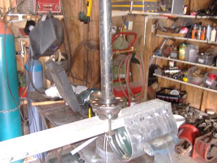
Pictured below is a DC permanent magnet generator that I have rebuilt. I got two of them from a junk yard and was able to make one good one. The above blade is made to fit directly onto the shaft of this motor. Notice the rust pits in the case, they were in pretty bad condition. It will produce about 5 volts DC at 60 rpm. To produce 14 VDC, such as used in charging batteries, it takes about 162 RPM. The internal resistance is measured at 3.9 Ohms.


Notice the front plate that I had to manufacture. The
large piece of aluminum is about 3/16 inch thick an about 7 inches in diameter.
The black circle that is around the shaft is a rubber seal to keep water
out of the bearing. The next circle in the plate, with the three screw heads
visible, is the bearing holder. The motor is from Imperial Electric and seems
to have been used on cleaning equipment. It is rated at 120 vdc 30 amps,
when used as a motor. I'm not sure but I think it is a 1 horsepower motor.
*****************************
That was then 2000. This is now, 2007! I have
moved to a new location with a hill top at 900' here in southeast Ohio and
have built the wind generator with the blade and motor pictured. Power
can reach 400 watts at times and I seem to be in a good wind location for
a class 1 area. (poorest for wind energy!) I use the power
to recharge a 12 volt deep cycle battery that powers my ham radio equipment.
It has been running since April of 2007 and I have not had to recharge
the battery on commercial power at all. The transmitter draws 22
amperes and I use it a lot! Receive is only 1.2 amperes.
I had to use 2 slip rings and two brushes to bring the
power out of the generator and down the tower. The slip rings are
mounted on a shaft that goes down the center of the axle bearing and has
two brush holders mounted in the mast. I used #12 wire to bring it
to my controller.
*********************
Here is the building process and the results:
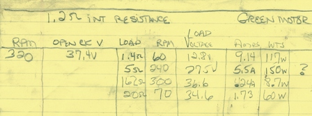
1 horsepower permanent magnet motor specifications as a generator.
Axle bearing, mast, generator mounted in aluminum channel and sheet cover.

Aircraft aluminum as tail TIG'd to channel and aluminum pipe.
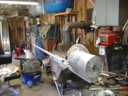
Ready for tower, with waterproof rubber "O" ring on shaft to protect bearing.
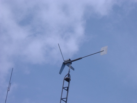
Up and flying at 50 feet above ground; 950' above sea level.
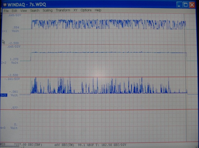
In this graph picture the top trace is the voltage output of the
wind generator,the scale is 1/10 of real voltage,
showing abourt 13.8 volts on peak. Actually scale is 6.54 volts/division.
The middle trace is battery voltage, also 1/10 scale,at 6.54 volts/division.
The bottom trace is the charging current into the battery. Scale
is 1.61 amperes/division.
Sept, 2007 Greg Weinfurtner