Select a picture for larger image.
1st local oscillator, mixer & IF. VNA-25 is used as the LO amplifier. ADE-25MH is used as the mixer. 3 dB pad on the LO input and a 6 dB pad on the RF output improve the mixer response. 1100 MHz IF output is the top connector, RF input is the middle connector, and the bottom connector is the LO tap.

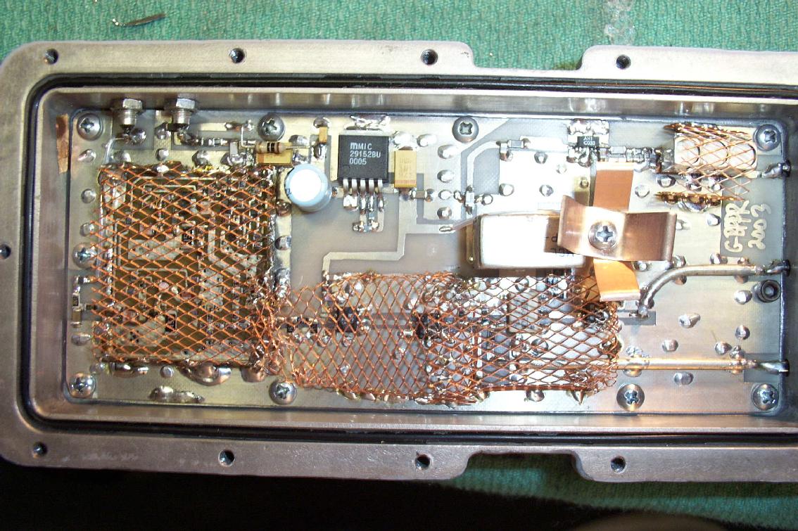
2nd local oscillator, mixer & IF. MC145152 and MB501 based synthesizer using a 12.8 MHz crystal (100 kHz reference) improve over the original 1170.7 MHz local oscillator. 1100 MHz IF input is the top connector, a test tap is the middle connector and the bottom connector is the 70.7 MHz IF output.
![[3rd_if]](3rd_if.jpg)
3rd local oscillator, mixer & IF. Remains mostly unchanged. 70.7 MHz IF input is the top connector, test tap is the middle connector and the bottom connector is the 10.7 MHz IF output.
![[resolution_filter]](resolution_filter.jpg)
Resolution filters. Remains mostly unchanged. Torroid coils are covered with Q-Dope. Trimmer capacitors are plastic dielectric. The bottom connector is the 10.7 MHz IF input (default 300 kHz filter) and the middle connector is the 10.7 MHz IF output.
![[log_amp]](log_amp.jpg)
10.7 MHz IF amplifier and logarithmic amplifier. RF input has a PLP-30 30 MHz lowpass filter and a 1:2 impedance matching transformer. IF Gain and Log Amp Cal pots are internal, as external ones are not needed after setup. Y Output is the top connector, 10.7 MHz IF input is the middle connector and the bottom connector is a test tap.
![[sweep]](sweep.jpg)
Sweep and X-sync generation. Uses multiturn pots for centering and calibration and LM833 op-amps for low-noise response.
![[newspec-1]](newspec-1.jpg)
New case pictures. Two military ammo boxes are mounted side-by-side. RF connectors all have dust caps.
![[newspec-2]](newspec-2.jpg)
Internal picture. RF section on one side and the power supplies on the other. Be sure to use linear power supplies to reduce generated interference.
![[newspec-3]](newspec-3.jpg)
Internal close-up picture.