This is a project for an add-on FM demodulator for a radio receiver, or other piece of test equipment, equipped with a 21.4 MHz IF output. This demodulator was designed specifically for use with a HP8569B RF spectrum analyzer and may require additional pre-amplification if used on other gear.
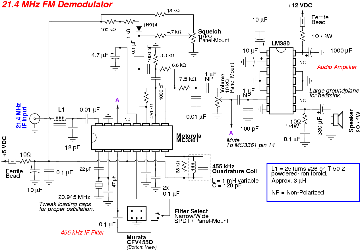
The FM demodulator is based around a standard Motorola MC3361 low-power narrowband FM IF chip. The MC3361 is no longer in production, but you can salvage them from older analog 49 MHz cordless phones and baby monitors. The 455 kHz quadrature coil and IF filter for the MC3361 can also be salvaged from the same circuit which you got the MC3361 from.
The MC3361 will also require a 20.945 MHz crystal (or 21.855 MHz) to convert the 21.4 MHz input down to the standard 455 kHz IF signal. These 20.945 MHz crystals will need to be salvaged from a FM two-way or ham radio which also operated with a 21.4 MHz IF. You may have to poke around your local hamfests and buy up a bunch of radios before finding one with the correct 20.945 MHz crystal. Be sure to note the value of the loading capacitors on the crystal for proper oscillation. These values may need to be tweaked a bit if the crystal doesn't oscillate.
An optional squelch circuit will also be added to the FM demodulator circuit. This squelch circuit will act just like the standard squelch control in a radio, only passing audio when the incoming RF signal reaches a certain level to avoid having to listen to "noise." The squelch level is set via a panel-mounted 10 kohm potentiometer. The squelch circuit is a little buggy and will still pass a little bit of audio noise when "squelched," but it's not a bit deal and I just left it.
The demodulated audio output from the MC3361 is then sent to a National LM380 2.5 watt audio amplifier to power an internal speaker. A standard National LM386 can be used if you only want to drive a pair of headphones or a lower power speaker.
The RF input to the MC3361 is via a simple LC network (3 µH / 18 pF) to match the incoming 50 ohms to the MC3361's impedance of 3300 ohms. You may wish to add a little bit of amplification on the RF input, if your application requires it. The MC3361 has a fairly low intercept point, so don't add too much gain or you'll just get distortion and intermodulation products.
An optional Filter Select switch will allow the bypassing of the narrowband Murata 455 kHz IF filter with a 0.1 µF capacitor. This is for when you need to listen to wider bandwidth FM signals. The overall sensitivity of the circuit will be reduced in this mode, which is common.
Review the datasheet for the Motorola MC3361 before constructing this circuit to get an idea of what the components do. Monitor the 20.945 MHz crystal's oscillation via a high-impedance oscilloscope and adjust the values of the two loading capacitors if it doesn't oscillate on startup. The quadrature coil can also be slighty tuned for minimum distortion when viewing the demodulated audio output on an oscilloscope.

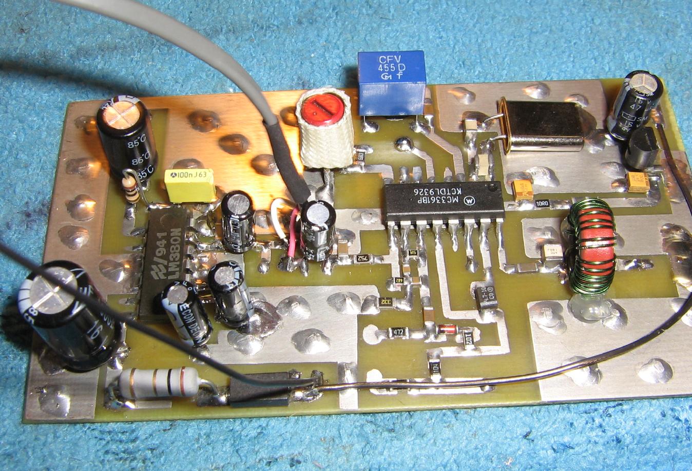
Overview of the 21.3 MHz FM Demodulator circuit.
The 21.4 MHz 50 ohm RF input is on the upper-left via the LC network feeding the MC3361.
The blue square thing is a Murata 455 kHz IF filter with a 6 dB bandwidth of +/- 10 kHz. Other similar IF filters will also work.
The variable core is the 455 kHz quadrature coil.
The silver rectangle laying down next the MC3361 is the 20.945 MHz crystal.
A 78L05 voltage regulator along the left-side powers the MC3361.
The LM380 audio power amplifier is along the right-side.
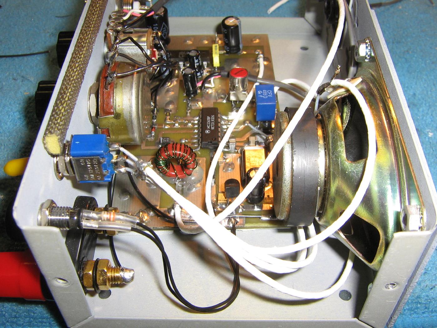
Alternate view.
The large ferrite bead and 1 ohm power resistor help to de-Q the LM380's power line to prevent oscillation.

Mounting the circuit board in an old printer switch case.
+12 VDC power input is via the banana jacks on the upper-left. A power-indicating LED and the Filter Select switch are above it.
The 10 kohm squelch potentiometer is in the middle of the panel with the 10 kohm power/volume potentiometer next to it.
The BNC jack is for the 21.4 MHz IF input.
A 5 watt / 8 ohm speaker was mounting internally inside the case. You'll need to cut out the rear of the case to avoid obstructing the audio output from the speaker.

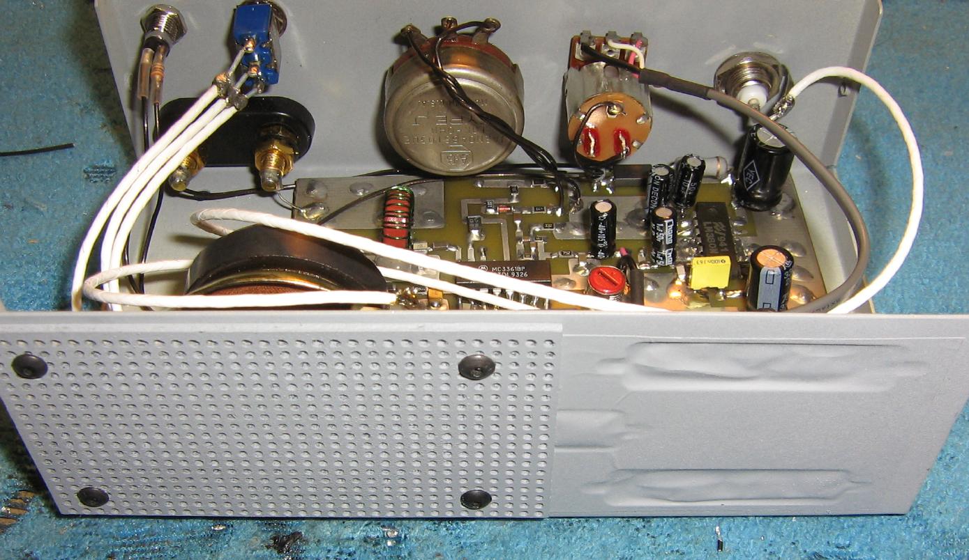
Alternate internal view.
The white wires are coaxial lines for the Filter Select and speaker connection.
Using coaxial cables for those connections is optional, but it will reduce the chance of receiving interference.
Internal side-view showing the installation of the rectangular 5 watt / 8 ohm speaker.
Use the LM386 instead of the LM380 if you only want to power a 1 watt or smaller speaker or headphones.
Completed rear-panel overview.
A piece of perfboard was added over the speaker's opening to act as a grill.
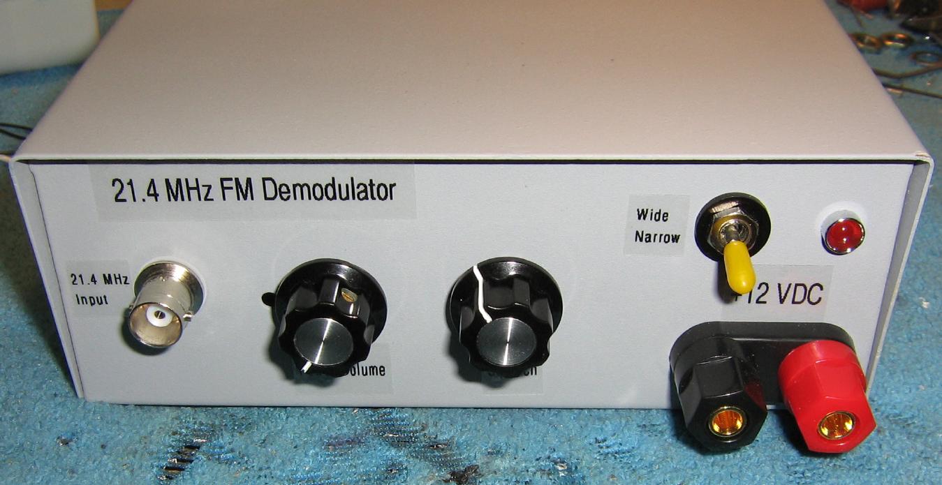
Completed front-panel overview.
The 21.4 MHz Input is via the BNC jack on the left.
The Power/Volume control is the potentiometer next to that.
The Squelch control is the potentiometer in the center.
Banana jacks on the lower-right provide the +12 VDC power input. The current draw can peak around 1+ amps at high audio volume, so take this into account.
Above the banana jacks is a power-indicating LED and the Filter Select switch.