Doodle Labs has a new product which should be of interest to any amateur radio operator wishing to experiment with higher-speed digital data in the 70 cm UHF band. The Doodle Labs DL435 420-450 MHz OFDM Transceiver provides high-speed data in channel widths of either 5 or 10 MHz throughout the 70 cm amateur radio band.
The DL435-30 transceiver has a standard 32 bit, 33 MHz miniPCI interface and works perfectly with a Ubiquit RouterStation. The RouterStation itself is powered via a standard power-over-Ethernet adapter. Note that the DL435-30 does have a fairly high current draw (around 2 amps) when run at full RF output power.
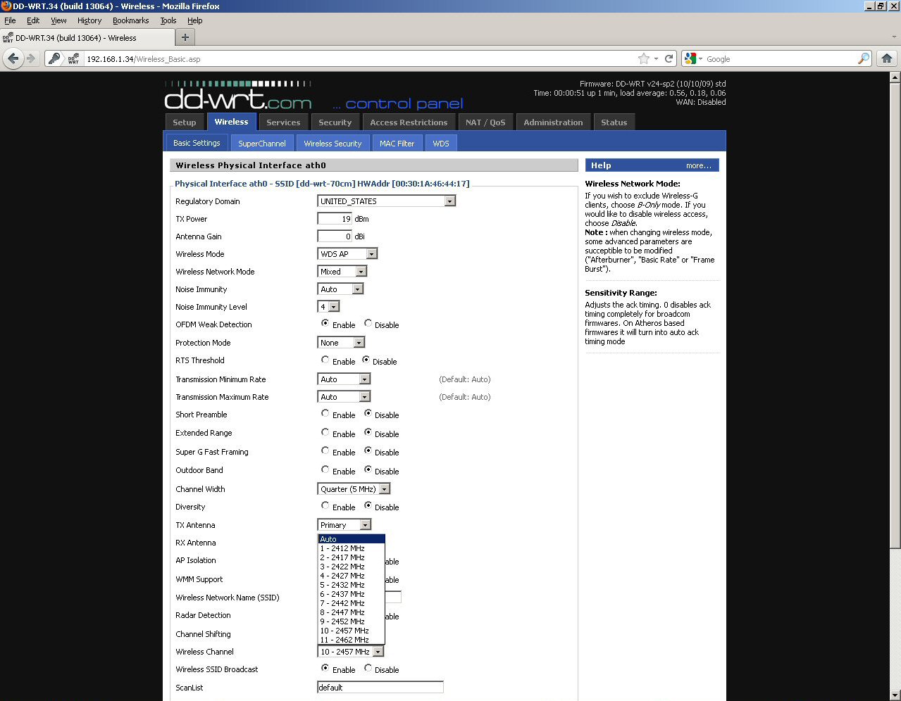
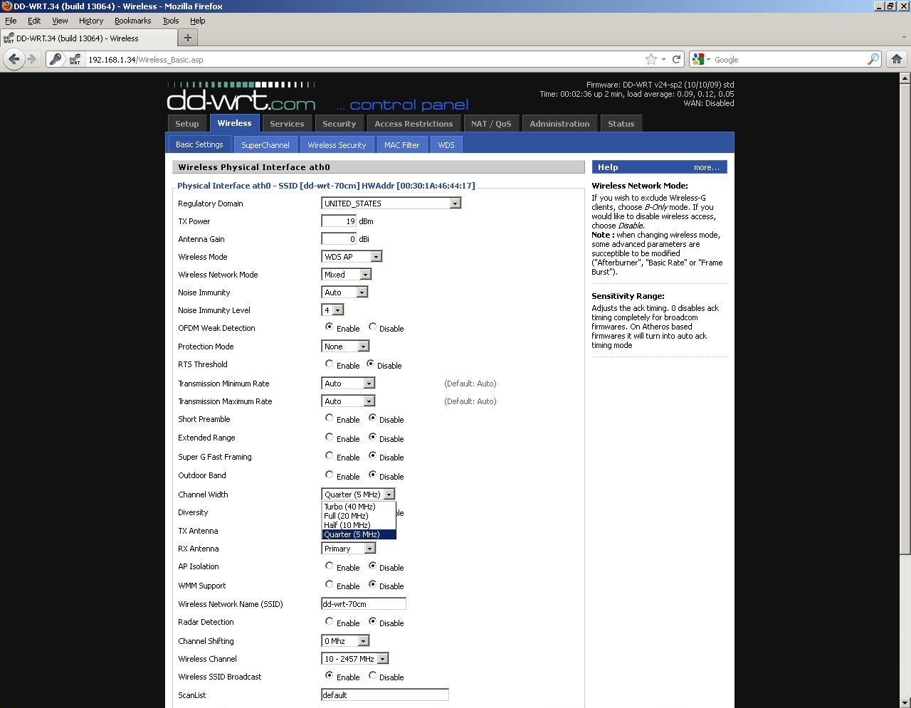
The Ubiquit RouterStation or RouterStation Pro can be running either DD-WRT or OpenWrt. Note that currently OpenWrt doesn't allow manual selection of with channel width (or at least we couldn't figure it out), so you may wish to try DD-WRT first.
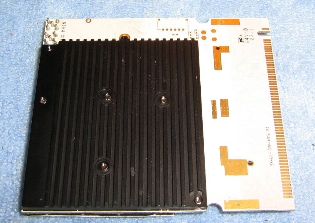
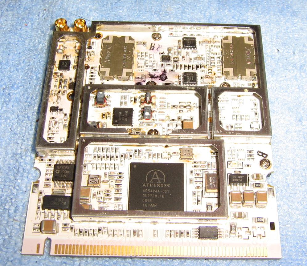
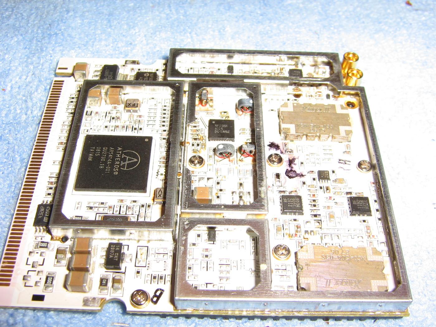
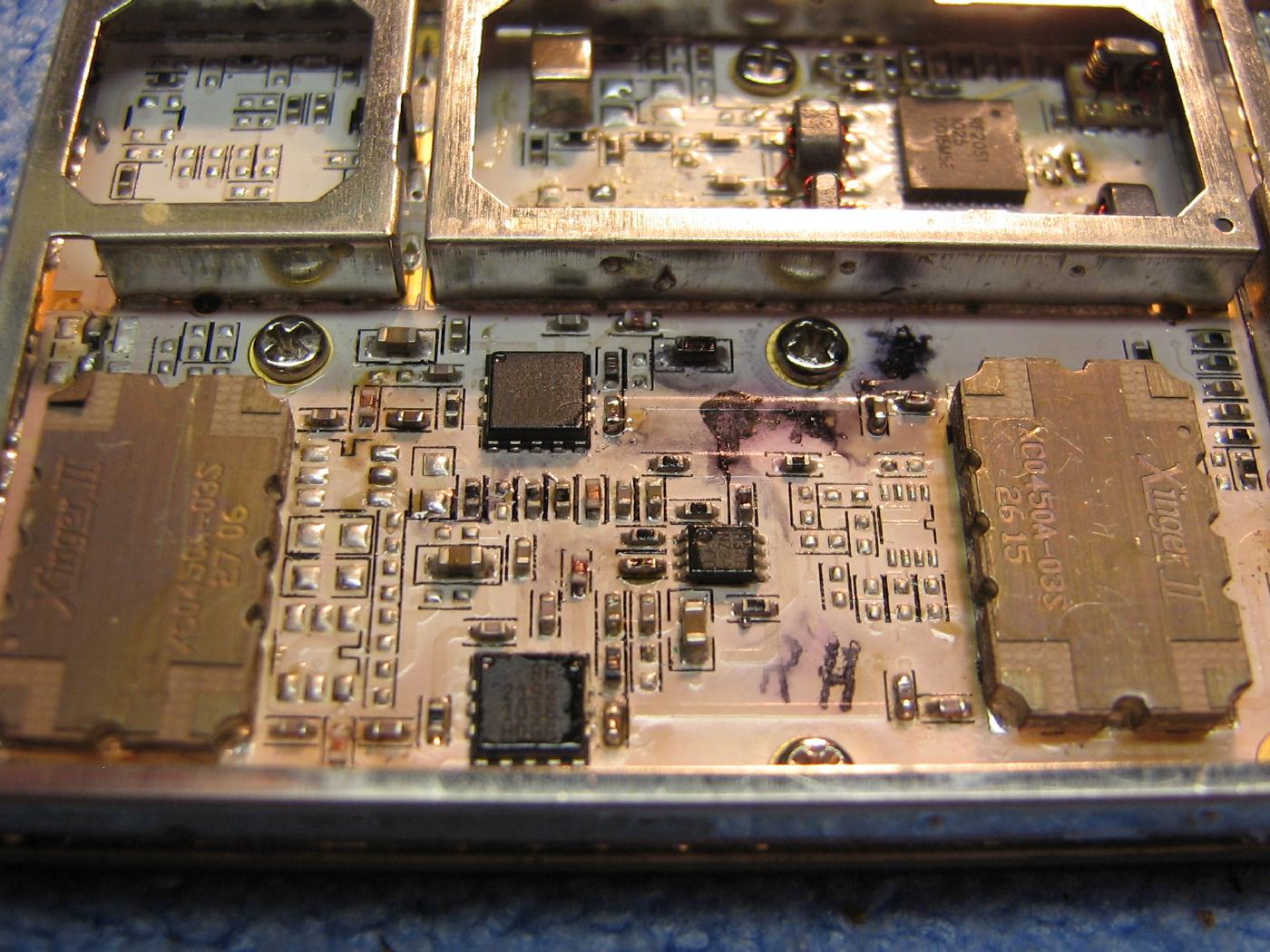
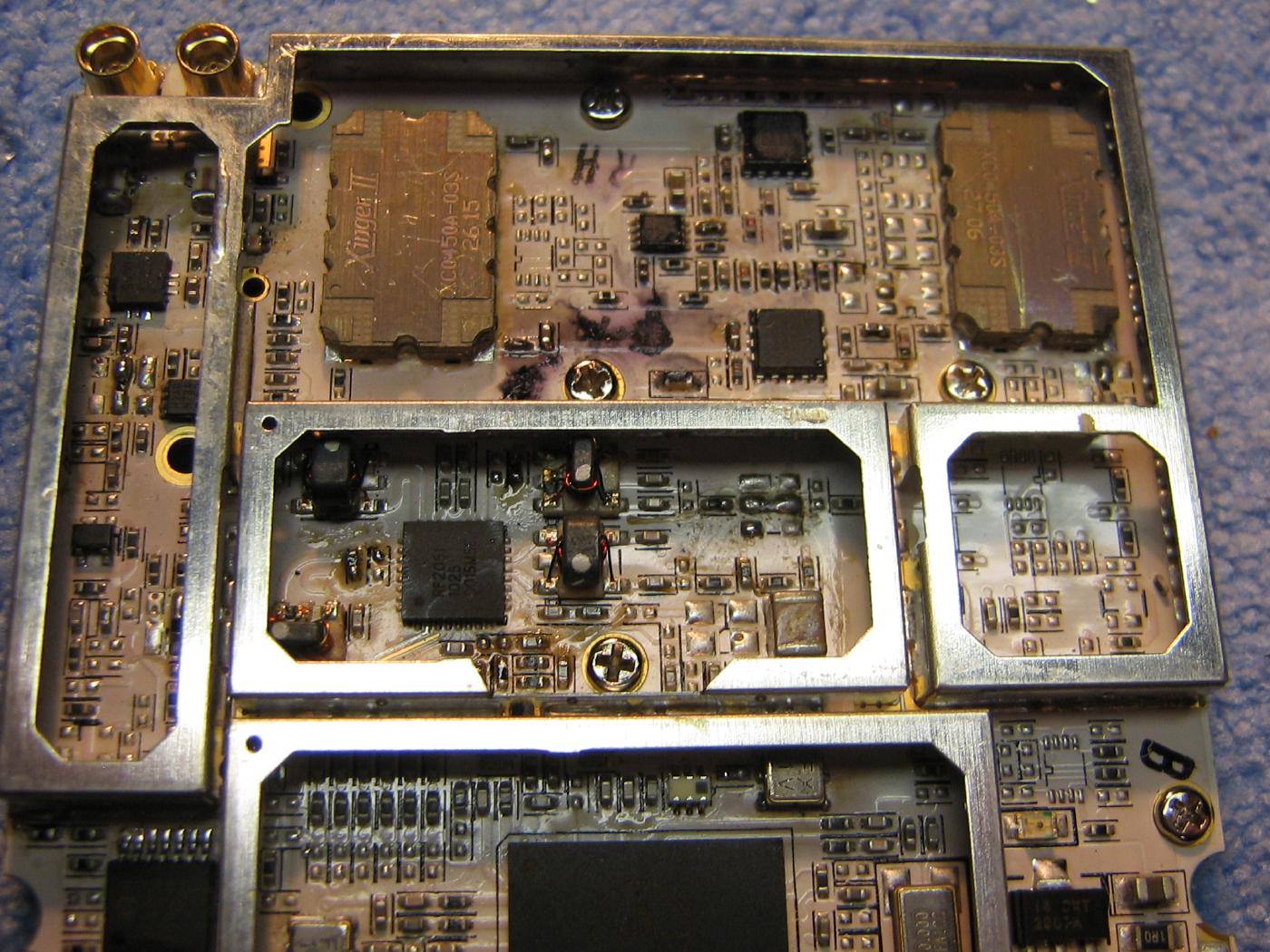
The DL435-30 transceiver is based around the Qualcomm Atheros AR5414A baseband processer and a RF Micro Devices RF2051 VCO and mixer. The DL435-30 transceiver itself "looks" like a standard 2.4 GHz 802.11g device in software, but the hardware is configured to provide a frequency offset of 2019.5 MHz. For example, if you select "2.442 MHz" in your configuration software the actual operating frequency will be at 422.5 MHz.
There are two channel widths available, 5 and 10 MHz, which are currently only manually selectable using DD-WRT and not OpenWrt. The 5 MHz channel width allows between 1.5-13.5 Mbps and the 10 MHz channel width allows for 3-27 Mbps. The modulation is Orthogonal Frequency-Division Multiplexing (OFDM) with 64 QAM, 16 QAM, QPSK, or BPSK depending on the received power level. The minimum sensitivity is around -97 dBm (for 1 Mbps). "Real-world" throughputs are around 7 Mbps for the 5 MHz channel width and 14 Mbps for the 10 MHz channel width.
Transmit power offset is an addtional +10 dBm, so selecting +13 dBm (20 mW) in your software configuration would give a final TX output power of +23 dBm (200 mW). The DL435-30 has an option for using diversity antennas, with one MMCX jack for the main antenna and one MMCX for the auxiliary antenna.
You should also note that the DL435-30 will "see" nearby devices operating in the 2.4 GHz region if the DL435-30 is not properly shielded or the 2.4 GHz device is operating at high power. Take this into account in dense RF environments.
With a 2019.5 MHz offset:
| 802.11g Channel |
2.4 GHz Center Frequency |
UHF Center Frequency |
10 MHz Channel Width - Lower Frequency |
10 MHz Channel Width - Upper Frequency |
5 MHz Channel Width - Lower Frequency |
5 MHz Channel Width - Upper Frequency |
| 7 |
2.442 GHz |
422.5 MHz |
417.5 MHz |
427.5 MHz |
420.0 MHz |
425.0 MHz |
| 8 |
2.447 GHz |
427.5 MHz |
422.5 MHz |
432.5 MHz |
425.0 MHz |
430.0 MHz |
| 9 |
2.452 GHz |
432.5 MHz |
427.5 MHz |
437.5 MHz |
430.0 MHz |
435.0 MHz |
| 10 |
2.457 GHz |
437.5 MHz |
432.5 MHz |
442.5 MHz |
435.0 MHz |
440.0 MHz |
| 11 |
2.462 GHz |
442.5 MHz |
437.5 MHz |
447.5 MHz |
440.0 MHz |
445.0 MHz |
| 12 |
2.467 GHz |
447.5 MHz |
442.5 MHz |
452.5 MHz |
445.0 MHz |
450.0 MHz |
802.11g channels 7, 8, 9, and 10 will be of most interest, as the converted frequency falls within the allocated Amateur TV (ATV) bandplan for the amateur radio 70 cm band. Note that in ITU Region 2 (U.S. and Australia) the 70 cm amateur radio band covers 420-450 MHz, while in ITU Region 3 (Canada / Europe) it's only 430-450 MHz.
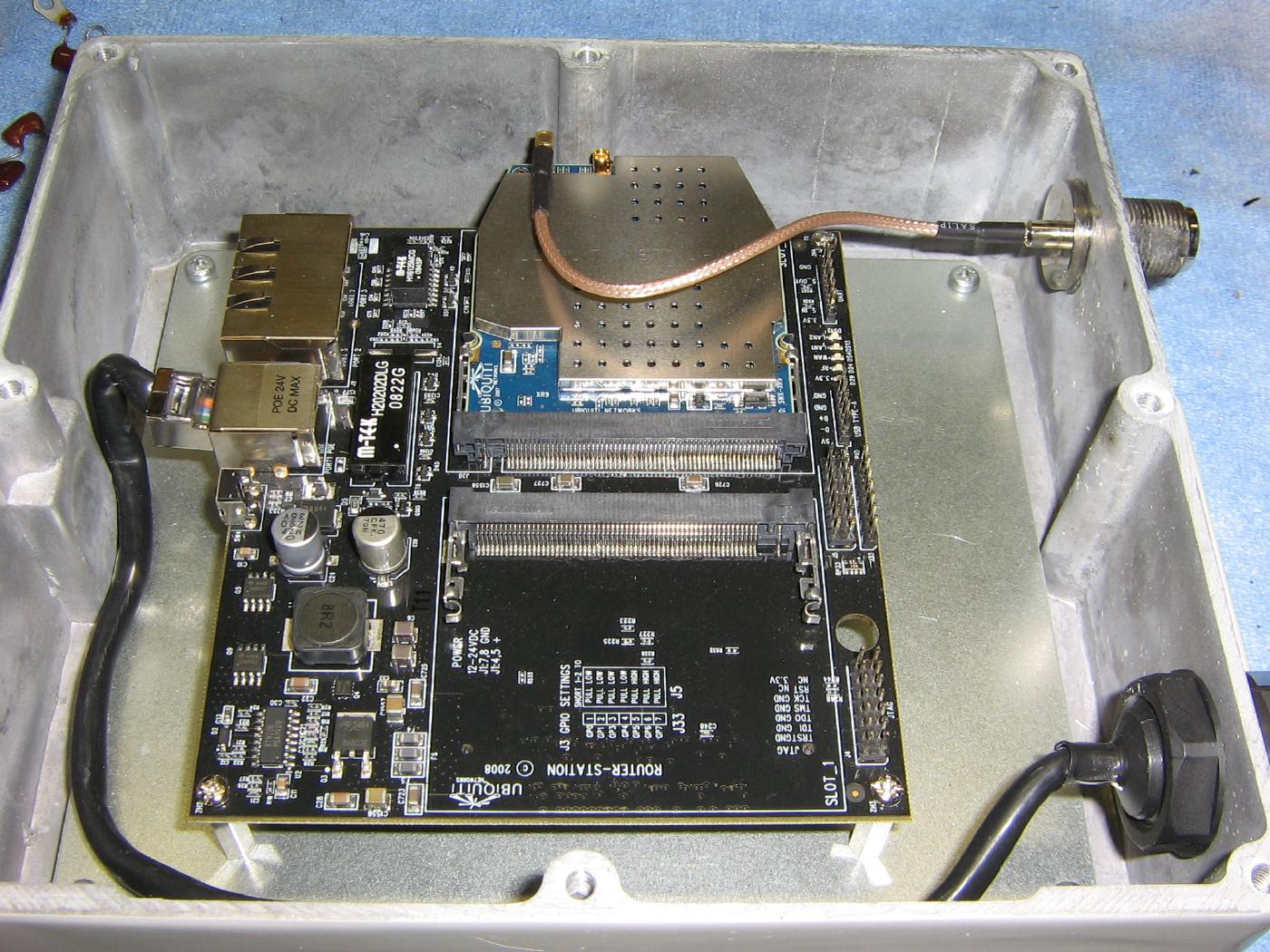
Overview of a Ubiquity RouterStation with a 900 MHz card installed.
It's mounted in a DCE-7x6x2 die-cast aluminum enclosure with a MMCX to N pigtail and a weatherproof Ethernet jack.
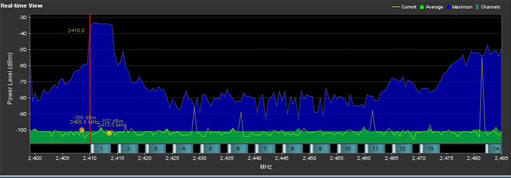
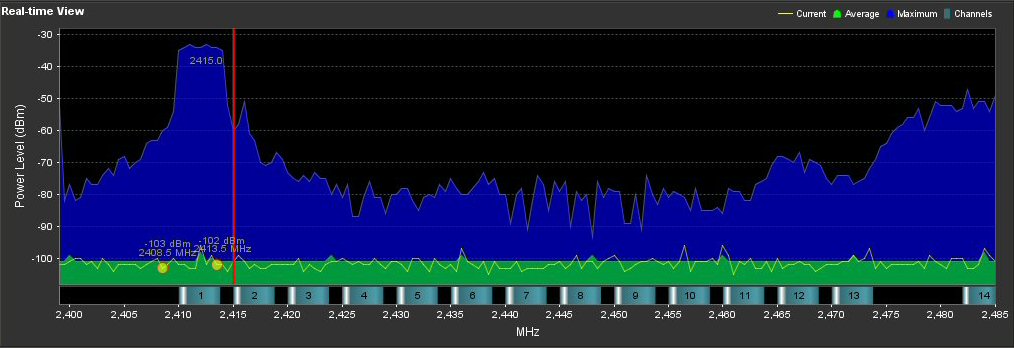
Example of a device operating in the 2.4 GHz band with only a 5 MHz channel width.