Using SwitcherCAD from Linear Technologies

There is a very, very good free Spice clone available from Linear Technologies called SwitcherCAD. Locate SwitcherCAD by entering "ltspice" or "swcad" or "switchercad" in any popular search engine. There isn't much reason to use others unless there is a spice clone currently installed. Several legacy (read: DOS) versions proved useful, but clunky. Other Windows versions are costly, huge, and sometimes cranky.

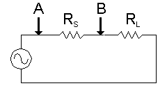
First, look at the filter as a short circuit. The circuit could be redrawn as follows:

series resistors

It is easily shown that when the voltage a point A is 10 volts, the voltage at point B will be 5 volts. Then calculate--

dB formula

With no filter at all, just a piece of hookup wire, there is a 6 dB insertion loss! SwitcherCAD calculates around that problem automatically.

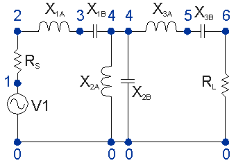
SwitcherCAD requires at least a mental image of a schematic diagram with the circuit nodes numbered, ground must be numbered with 0 (zero). Other nodes can be numbered in any order. Numbers may be skipped.

spice diagram

Take this 3rd order bandpass filter as an example. The center frequency (arithmetic center) is 1 MHz and the pass band is 500 kHz. These are the elements generated for a tee input filter with 50 Ohm termination resistances.

Filter Elements
XnAInductor HenriesXnBCapacitor Farads
X1A1.59155E-05X1B1.69766E-09
X2A2.12207E-06X2B1.27324E-08
X3A1.59155E-05X3B1.59155E-05

...continuing...

Here is an annotated netlist which shows how SwitcherCAD functions. This should be enough to allow examinination of any passive LC filter. SwitcherCAD has powers far beyond those shown here, but the immediate goal is to view the response of a passive LC filter.

The basic syntax is a letter: "C" for capacitance, "L" for inductance, "R" for resistance, "V" for voltage source. Next are two numbers. These are the two nodes to which the device is connected. Finally, the value of the device is displayed. Each piece of information is separated from the other by one or more spaces.

In each case the component designation is followed with no space by an identifier. Identifiers 1, 2, 3, etc., are shown. Other possibilities are Rsource, Vpower, Vsignal, and Cinput, for example.

SwitcherCAD assumes the units of resistance, capacitance, inductance, and frequency are Ohms, Farads, Henries, and Hertz respectively. For resistance and frequency, append "K" and "M" for kilo- and mega- as in 100K or 1.5M. For capacitance and inductance, append "U" for micro-, "N" for nano-, and "P" for pico Farads or Henries as in 50P or 180U. Lower case letters seem to work as well.

Refer to the numbered schematic diagram above to follow the positioning of the components in the net list.

R1 1 2 50

A resistance is connected from node 1 to node 2. The value of the resistance is 50. This is our source resistance.

L1 2 3 1.59155E-05

An inductor is connected from node 2 to node 3. This is half of the input series-resonant circuit.

C1 3 4 1.69766E-09

A capacitor is connected from node 3 to node 4. This is the second half of the input series-resonant circuit.

L2 4 0 2.12207E-06

An inductor is connected from node 4 to node 0, ground. This is half of the parallel-resonant circuit which forms the vertical portion of the tee filter.

C2 4 0 1.27324E-08

A capacitor is connected from node 4 to node 0, ground. This is the second half of the parallel-resonant circuit which forms the vertical portion of the tee filter.

L3 4 5 1.59155E-05

An inductor is connected from node 4 to node 5. This is half of the output series-resonant circuit.

C3 5 6 1.69766E-09

A capacitor is connected from node 5 to node 6. This is the second half of the output series-resonant circuit.

R2 6 0 50

This resistor, connected from node 6 to node 0, ground, represents the load placed on the output of the filter circuit. Its value is 50 Ohms.

V1 1 0 ac 2 sin

The "V" identifies a voltage source with no internal resistance. Since this is an AC source with no offset, a reversal of the zero and one is allowed. For information on other sources, read the SwitcherCAD help files.

The voltage source is "AC." It is sinusoidal with 2 volts peak. Considering the losses in the source and load resistances, use two volts peak. This allows the software to show 0 dB loss in the pass band instead of forcing us to calculate around the 6.02 dB loss in those resistances.

.AC LIN 100 500K 2000K

This is a SwitcherCAD "dot" command and instructs the software to do a linear sweep (LIN) in 100 linearly spaced steps from 500 kHz to 2000 kHz. It is possible to use "DEC" for 100 steps per decade. In this case, thats 100 steps from 500 kHz to 5 MHz. Use "OCT" for 100 steps per octave. That's from 500 kHz to 1000 kHz and again from 1000 kHz to 2000 kHz.

.SAVE V(6)

This is a SwitcherCAD "dot" command and instructs the software to save only the data from node 6, our output node. Monitor additional nodes by adding additional V(n) components to the list, each separated with a space.

.END V(6)

This is a SwitcherCAD "dot" command and tells the software that no further commands exist in the main portion of the list. There are many more dot commands and many, many more attributes to explore.


R1 1 2 50

L1 2 3 1.59155E-05
C1 3 4 1.69766E-09

L2 4 0 2.12207E-06
C2 4 0 1.27324E-08

L3 4 5 1.59155E-05
C3 5 6 1.69766E-09

R2 6 0 50

V1 1 0 AC 2 SIN

.AC LIN 100 500K 2000K
.SAVE V(6)
.END

Here is a complete listing of the third order tee filter with center frequency of 1000 kHz and a passband of 500 kHz. This was provided for an easy copy-paste into a rudimentary text editor, such as NotePad. The software appears to need a blank line to begin the netlist.

After the cut and paste, save the file with an extension of "cir" so that the entire name looks like filename.cir.

Launch the SwitcherCAD software by clicking on its SwCAD icon and then open the file just created. The only weakness in the software seems to be that a net list cannot be created. First, create the net list in a text editor. Do a copy-paste of the netlist at the left and save it as a text file with '.cir' as an extension. For instance, 'bp-third.cir'. Once the netlist is created, any amount of editing can be done within SwitcherCAD. It is possible to create a schematic in SwitcherCAD and go from there.


HTML 4.01 Validation