Overview
This is a simple 2.4 GHz SWR meter which is based around surplus microwave hardware which can be easily found. The main component is a MECA -20/-20 dB Directional Coupler which has a frequency range of approximately 700 MHz to 2.5 GHz. This particular directional coupler has two ports, each coupled by 20 dB. What that means is, a signal is "coupled" to these ports which is identical to the main signal passing through the directional coupler, only it's attenuated by 20 dB. By placing diode detectors on the outputs of these two ports and comparing the resulting voltages on an oscilloscope, you can quickly determine the integrity of your antenna system in reference to 50 ohms.
Directional Coupler Block Diagram
Operation
Be sure to measure SWR at the antenna! Feedline loss will attenuate the signal and give you a false SWR reading if you measure it directly at the transmitter's RF output. Don't be like those guys at Field Day who brag about their radio's (internal) SWR reading when connected to a homebrew antenna with 200 feet of Radio Shack RG-58 and banana clips.
Also, don't trust "analog" movement reading SWR meters when dealing with digital data transmitters. The needle response time isn't fast enough to provide an accurate reading.
Pictures
Click on picture for larger image.
![[24swr-1.jpg]](small/24swr-1.jpg)
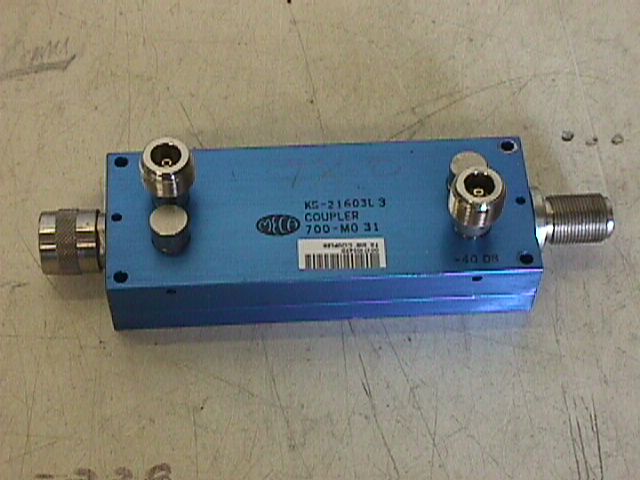
Overview of the hardware components used. The directional coupler is the large blue thing. A N-connector female-to-female adapter is needed to connect the Narda 5 Watt, 50 ohm load. The diode detectors are the silver things on top. They both are identical and house 1N23 point-contact diodes. Their voltage output is via integrated BNC connectors.
![[24swr-2.jpg]](small/24swr-2.jpg)
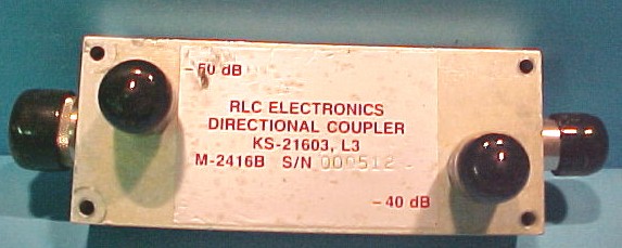
Close up view of the diode detectors. They are sometimes referred to as "crystal" detectors. 1N23-style diodes can be hard to find. Fair Radio does carry them. You can also find them used as mixer diodes in some 10 GHz gunnplexer-based automatic door openers.
These particular diode detectors generate a negative output voltage. Remember that when looking at the oscilloscope screen shots.
![[24swr-3.jpg]](small/24swr-3.jpg)
Test setup. A Proxim Symphony Cordless Gateway is used as the 2.4 GHz signal source. The black cables connect directly to the oscilloscpes inputs.
![[24swr-5.jpg]](small/24swr-5.jpg)
Oscilloscope screen showing the voltage outputs from the diode detectors. The top trace is the forward port, or the diode detector closest to the signal source. The bottom trace is the reverse port, or the diode detector closest to the antenna/load.
This setup is transmitting into a pure resistive 50 ohm load, so the bottom trace is showing no voltage output (very low SWR).
The scope settings are: CH1 (top) 20 mV/div, CH2 (bottom) 10 mV/div (both DC coupled).
![[24swr-6.jpg]](small/24swr-6.jpg)
Oscope screen close up of the above. Everytime the Symphony Gateway transmits, a negative-going voltage pulse is sent from the diode detector. The same thing happens in reverse, it's just that nothing is showing up because the output impedance of the Symphony Gateway is equal to the load impedance (50 ohms), which is resulting in a low SWR.
![[24swr-7.jpg]](small/24swr-7.jpg)
Oscope screen shot with the 50 ohm load removed. The Symphony Gateway is now transmitting into an open load, or a worst-case impedance mismatch situation. Note the large spikes on the bottom trace. This represents a large, unacceptable SWR.
The scope settings are: CH1 (top) 20 mV/div, CH2 (bottom) 20 mV/div (both DC coupled).
![[24swr-8.jpg]](small/24swr-8.jpg)
Now the directional coupler's output is connected to a 12 dBi MMDS (2.5 GHz) corner reflector antenna. Note the large forward spikes with only small reverse spikes. This is an acceptable SWR.
The scope settings are: CH1 (top) 20 mV/div, CH2 (bottom) 10 mV/div (both DC coupled).
Notes
It's possible to convert the diode detector voltage output's into a real SWR value, but it's usually easier just to view the oscope screen as you tune the antenna.
Directional couplers with mismatched coupling ratios (say one's -40 dB and one's -50 dB) will also work, if you add a resistive attenuator pad to the lower valued port to make the coupling ratios equal.
Return to Green Bay Professional Packet Radio for more info and contact information.
![[24swr-1.jpg]](24swr-1.jpg)
![[24swr-2.jpg]](24swr-2.jpg)
![[24swr-3.jpg]](24swr-3.jpg)
![[24swr-5.jpg]](24swr-5.jpg)
![[24swr-6.jpg]](24swr-6.jpg)
![[24swr-7.jpg]](24swr-7.jpg)
![[24swr-8.jpg]](24swr-8.jpg)