"A Progressive Communications Receiver"
alias
"A High-Performance Communications Receiver"
....this time its personal.
"A Progressive
Communications Receiver" November '81 QST by W7ZOI, Wes Hayward and
K5IRK, John Lawson.
Subsequently also published for several years as a design in the ARRL Handbook circa '85 - '90 as "A High-Performance Communications Receiver".
Subsequently also published for several years as a design in the ARRL Handbook circa '85 - '90 as "A High-Performance Communications Receiver".
It is the purpose of this webpage to document my second attempt at this project starting with the 80m core receiver first and also having the parts on hand for then adding the first dual conversion band (40m).
While intrigued by radio and beginning to study for my first Ham ticket in 1992, I attempted and completed construction of this project.
I thought I did a great job at it, etching all the boards, everything in shielded boxes, beautiful tilt-front steel enclosure from Newark, KVG CW filter, and even a lighted-recessed vernier dial face waiting to be calibrated with the internal crystal marker generator. It was really somthing I thought, but it never made a sound.
The whole thing was deader than a door knob. Not even a hint of static for the new ham.
Despite much disassembly, testing and troubleshooting, component replacement, etc, the project was eventually shelved in the basement where years later it fell victim to a basement cleaning.
17 years, and several kits and homebrew rigs later, I am going to start over and try this project again. Its my goal to complete a multiband version of this receiver, and perhaps even compliment it eventually with a matching homebrewed multiband transmitter, as I truly enjoy the thrill of operating equipment made at home.
The project will not happen 'overnight' or in a weekend, or save me a ton of money - but I will certainly learn alot along the way and hope to someday have a pair of homebuilt multiband 'twins' on the air at this operating position.
Designers Mr. Lawson and Mr. Hayward have already offered their encouragement and assistance as they selflessly have with so many others.
06/09
- email from W7ZOI offered new matching network for alternate INRAD crystal filter (Lower 200ohm filter impedance).
- All parts sourced for the initial 80m/40m version of the receiver and saved to spreadsheet.
- From the notes included with my original, returned QST article info packet (From SASE + $ sent to ARRL in ~1992) all component identification numbers on circuit board layouts and board templates provided are from the original QST article, and DO NOT match subsequent ARRL Handbook component numbering, as components were re-numbered for publishing in the Handbook articles.
- I may consider using some of AA3SJ / W3TS modifications to the receiver later in the construction process after just getting the modules working first.
07/09
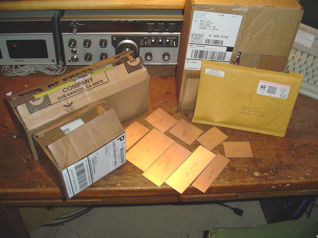
- All parts ordered - less INRAD experimenter's filter kit. Its time to start on some circuit board fab.
- Parts arrived and all the boards have been cut. Here we go....
07/26/09
- The AF AMP/ Product Detector board has been completed, and it works!!! That is if I touch the output of the mixer with my finger I can hear the hum in my phones. It gets louder and softer when I turn the gain pot back and forth - so I think the amplifier is OK. The testing of the detector/ mixer itself before the amplifier will have to wait until I get some more boards done.
- I fabricated the AF AMP board using a 'new' board circuit transfer technique that I found online utilizing a laser printer to print a reversed circuit image on glossy photo paper, then ironing that on to the board for the resist. This board was actually done with a light weight matte photo paper. For the next board I picked up some lightweight glossy paper to try.
07/29/09
- Preselector board completed. I chose the 3.5-4.0 Mhz version since will hopefully be making converters for each band. I tried the different photo paper for this board transfer (Brother Premium Glossy Photo Paper 51 lb 190g/m2 weight) since was locally available. The transferred toner is much thicker and tougher than the matte paper I used on the previous board. There was no 'pinholing' in the pattern, and I did not have to "Reinforce" any of the pattern with the Sharpie marker. The down side is had to spend a little more time rubbing paper off and going around some of the copper traces with a plastic alignment tool to loosen up the paper in tight areas. I like this paper better. I paralleled pairs of 5% silver mica caps to arrive at the 420 and 650pF values (200+220 and 620+30).
For testing the preselector, I ran scrap RG58U from the preselector output to the antenna jack of my Ten Tec RX tuned to 80m band. The 365pF air variable cap was temporarily wired to the board and a 1ft. wire was also soldered to the the input of the board and the other end of this wire just lay on the table. With the Ten Tec tuned at any 80m freq, I could peak the noise with the variable cap. Looking good.
Next I fired up the old Heathkit signal generator and turned the RF gain on the Ten TEC RX way down. I was able to peak the RF signal and swing the S meter on the Ten Tec at 3.500 and 4.000 Mhz with the variable cap plates still having some meshing at both ends - so I think I ended up in the freq. range I was supposed to be in. Good check I think.
07/30/09
- The BFO board is assembled and its "BFO"ing! I am not sure if I am
done with it yet though. Will have to see how it goes with the
basic 80m RX or ask for some advice. I may have a problem with the
tuning frequency of it. I was thinking it should be tunable 700 or 800 Hz above and below the 9.000 mhz IF..
My old S&S freq counter was calibrated maybe 15 years ago in a avionics lab so accuracy is questionable now, but it shows the BFO 9.000.0 Mhz with the plates full meshed on a 45pF air variable. With the plates opened about 9.000.5 Mhz. So around 500 Hz of rubber and in the wrong direction I think.
I was planning on just using one BFO with a panel mount air variable for upper and lower sidebands. I know either one would work for CW RX, but was hoping to hear some SSB as well. So I will see how this BFO does in the assembled basic RX.
Could also be that the crystal I used is one of those smaller styles which I read somewhere they do not 'rubber' as well as HC-6U. I may consider increasing the windings on the primary of transformer from 35 to say 40 also, but will ask for some help on this.
Also confusing me is checking my book references and online websites I get different results about if USB/LSB then BFO is above/below IF. Need to nail this down. I am not against building 2 of them with switching if necessary.
For testing the BFO I just put the counter on the output and adjusted the "Tune" mica trimmer until it started, then peaked same trimmer for max output using a RF probe with the BFO hooked up to the AF AMP board.
For another test - with headphones connected to the AF AMP board, I tuned my sig, generator across 9 Mhz on the table figuring the BFO would beat against it. It did! I could vary the pitch of the audio with the air variable cap (But will need more range there if I stay with panel mount BFO).
This board took some extra time building the 12v power input network "Manhattan" style right on the corner of the BFO board. It fit OK there I think. I also used "Manhattan" mounting for the mica trimmer.

08/05/09
- A single mixer board is completed. I am not sure of a good way to test this one yet though as am afraid to couple my signal generator directly to the board. (Even with it selected for lowest output, I have gotten shocked from my sig gen many times.)

08/08/09
- VFO board completed. Output is good on a freq counter. This was a fun board. I like building LC oscillators as they always seem to need a bit of tweaking to get them where you want. This one was no exception, but only required minor experimenting by compressing the L6 coil windings and adjusting the capacitance value at C3. I would think this is normal due to construction differences.
When I first checked the VFO, it was running 4.57-4.96 Mhz with 1/2 CT trimmer, so I was low and needed to expand the tuning range as well for the target 5.0-5.5 Mhz. I studied the component table in the article for different freq's and I think was successful by changing C3 from the 120pF to a 62pF with a 15pF in parallel with it. I am lucky I had these values (And they were NPO's!) in my junk box.
The final tuning range with CT trimmer at midrange is 4.97-5.52 Mhz for 550 Khz range. Of course this leaves me with a bit more tuning cushion than is ideal, but I think its better to have some tuning cushion at both ends. Too much tuning cushion though would just eat up band spread and probably make any tuning adjustment that much coarser, so I wanted some cushion over the 500 Khz, but not alot.
I was also pleased this board worked because this was the first circuit board requiring the dreaded "Dual Gate MOSFET". I knew these pricey little transistors were very susceptable to static damage and so I was little nervous about that too. There were not one, but TWO typos on the circuit board component placement diagragm for the VFO. Q6 and Q7 were swapped, and the center tap and ground connections of L6 were labeled as going into the wrong holes as well. These kinds of things are probably among the culprits that got me 17 years ago.

It looks like just one more board left for the basic 80M receiver - and that would be the the very 'busy' IF AMP board. It is no accident I am saving this board for last. I think everything is working so far, I'm in practice now, have a little bit of confidence, and 1/4 lb. of solder left :)
08/12/09
-IF board completed, less any crystal filter or the filter matching networks. I tried to be very careful around Q9 and Q10. I grounded the circuit board holding fixture, then touched the solder iron to the fixture just before soldering up the Dual Gate MOSFETS.
I almost made a mistake and soldered one secondary lead of T4 into wrong hole but caught my error later during the work. I am all for ground plane construction, but I think stuffing a board with many components close together such as this, it was actually a good thing that I chose single sided board as I could actually see the traces through the material aiding proper installation.
Although on this board component overlay drawing I noticed that the 100 and 560 ohm resistors above Q9 are swapped in the wrong holes, so I installed them in eachothers' positions so they agree with the schematic. My board artwork is as supplied from the ARRL in 1992 - so hopefully this is corrected on current copies.
There is also a pair of hand written corrections from the ARRL on the supplied drawing about adding a 2.2k resistor across the primary of T4 and a typo correction where one of the two 1M AGC resistors is mistakenly indicated as a 1K on the component overlay.
I mounted the C16 trimmer manhattan style again and applied power to the board for a smoke check. Checked OK, so then proceeded to adjust the R10, AGC SET trimmer - but was getting some weird readings. When I was still getting voltage readings with the DMM no longer connected to the IF board I decided to try another meter. Yep it was the batteries in the first meter! What is my luck of checking out somthing with another thing that itself does not work! Anyways AGC no signal voltages were easily adjusted per the article with the second DMM. Wheww!


08/13/09
- Spent some time temporarily hooking up all six boards to power and eachother per the flow diagram, powered them up, hooked up my loaded 80m inverted vee antenna and was rewarded with first signals on 80m!!! There is no filter installed as was my intent to try testing without one installed, but there aren't that many signals on 80m in August either :)
The action of the preselector on this receiver is really incredible and I can tell right now it is going to take 2 hands to tune it :) It was even driving a small 4" speaker so that I could hear the stronger signals without headphones on, but the AF board is not designed for speaker operation. I will try to get a testing picture here very soon, but is so good to know that my second time around with "The Progressive Receiver" I am coming out OK.
I need to get some advice on my BFO frequency and possibly change to a larger, more 'rubbery' crystal for my panel mounted BFO, or may end up obtaining the INRAD 9.0 Mhz LSB & USB crystals then make another BFO to cover both sidebands with a switch. I will get this issue ironed out and then begin work on the other mixer, 40m oscillator, and 40m filter boards.
08/16/09
- More helpful emails from K5IRK and W7ZOI suggest that I need to get a full size 9.000 Mhz crystal in the BFO board for better VXO range as is required using a single BFO for USB and LSB.
- Uploaded a YouTube video of this board work so far spread out on the workbench and listening on 80m.
"A Progressive Receiver First Signals"
08/17/09
- I read at one of the online references for laser toner circuit board etching (Bottom of page) that coating the board with a clear spray will preserve the copper while still allowing decent solderability. I did not believe this - but thought I should try it.
So I performed an experiment on scrap circuit board. Sprayed the copper side with clear enamel, let dry one hour, then tryed soldering through the enamel. It just took a extra couple of seconds for the iron to do its work, but the solder job turned out great! It is my plan then on future boards after soldering all components in to coat the copper with clear enamel to preserve the state of the copper. I should only have to solder a few inter-connections on any board afterwards anyway.
08/18/09
- INRAD Experimenter's Filter Kit and larger replacement 9.000.0 Mhz BFO crystal ordered for better VXO range. I elected to start with the 2400Hz filter model as I like using the wide bandwidth to search the band first.
I plan on adding at least one active audio filter, so the idea at this point is 2400 Hz IF filter with active AF filter for CW unitl I get around to adding another CW bandwidth IF filter. However I will install IF filter switching circuitry with this first 2400 Hz IF filter.
08/20/09
- INRAD parts arrived ....2 days to IL from CA via cheap method is FAST. I am impressed that they included regular leaded caps in addition to the SMD caps in the crystal filter kit (Your choice). This eased my mind as I really did not want to get into SMD anyway.
INRAD 9.000.0 BFO crystal installed and definately 'rubbers' much better than the smaller one from Mouser. I measured a 4.5 Khz swing now with my 45pF air variable.
08/22/09
- First mixer, 40m oscillator, and 40m filter boards etched. First mixer board assembled.
08/25/09
- Completed the 40m converter oscillator using a 3.300.0 Mhz crystal from Surplus Sales of Nebraska. However during testing I got my first 'wiff' of smoke that I believe came from the 39 ohm resistor of the DC power input network. I had this network mounted on the 1st mixer board so that I only had to build one of these networks for the converters oscillators, and the DC would be switched with the oscillator inputs. I substituted the DC input network from the BFO into the 40m converter oscillator for troubleshooting, but then got a wiff of smoke from that network too, so I knew the problem was in the 40m converter oscillator board.
Really there was not that much going on with the converter parts - but after double checking everything I decided to rewind T3.
As it turns out that was the problem as it then fired right up, tweaked it for max output and reliable starting, and was right on freq.
I am fairly certain that I did not have primary and secondarys crossed up. What I think it was is the CT relationship to the primary leads as its not really a CT but rather a tap at 13 of the 65 turn primary. I had to lay this crystal down as the leads could not be bent. Glad everything worked out.
On with the 40m input filter next.

08/30/09
- The 40m input filter has been completed a couple of days now. I have coarsely aligned it using the old Heathkit signal generator. There is no RF amplifier called out for 40m - hence the jumper wire between points X and Y on the board. I am been working through some issue(s) on 40m though. There is no band noise at all. I have only been able to hear a couple of 40m signals very, very faint one time when connected to my 40m vertical antenna. I have done alot of board swapping, component swapping, re-winding, measuring, etc., but am still stumped on why 40m is 'dead' with or without the 40m input filter inline with a sig gen or on the air to antenna.
John Lawson, K5IRK, has been working with me via several emails on this problem and seems as determined as me to get to the bottom of it.

09/03/09
- Well after several more helpful emails from John Lawson, finally stumbled in to my problem on 40m. I had installed the windings for the T5 bifiliar matching transformer in the wrong transformer holes on the mixer boards. This was also the case on the second mixer. These transformers are still not intuitive to me as they are drawn schematically, but hey I still don't get Roman numerals either :)
With these two circuit corrections, the PR RX came to life on 40m, and is even better now on 80m.
I have some tidying up to do on the boards after double checking the AGC control circuit. Then will be time to order some parts for the other bands, and enclosure, accessory circuits, etc.
Plenty to do still, but think I have now succeeded where I failed the first time, all those years ago. The challenge of a multiband RX seems within reach now.
In my opinion it is a testament to the designers, using the careful selection of parts that they did in 1981, that the Progressive Receiver can still be duplicated with semiconductors some 28 years later.
09/20/09
- Looks like the next pair of band modules (20 & 30m) will run about $30 each. I am thinking its more important to get the RX in an enclosure at this point.
I am considering one of the Ten Tec or Circuit Specialists enclosures right now.
Also thinking about the AADE DFD2 digital dial which would appear to work nicely for a dual conversion, multiband RX.
But first I ordered the parts for five accessory boards I wanted to try in this PR RX. Some I have built previous examples of for past projects.
These accessory boards include:
"Filter Switching with Diodes" for later addition of a 600Hz IF filter (W1FB QRP Notebook), "A Switched Variable Selectivity Audio Filter" (W1FB QRP Notebook), "An Audio Derived S Meter" (W1FB QRP Notebook), "Tunable Notch Filter" (W1FB Design Notebook), and a 5 watt audio power amplifier for speaker operation using the TDA2611A in a cloned circuit from the Ten Tec 1253.
The S meter and audio filter boards have been prepared for components.
09/27/09
- "An Audio-Derived S-Meter" (p.57 W1FB QRP Notebook), and "A Switched Variable Selectivity AF Filter" (p.67 W1FB QRP Notebook) were completed and tested OK.
I ordered extra 2200pF poly caps for the AF filter and took the closest ones. I also started matching of the appropriate resistors, but quickly found it uneccessary as I had ordered some 1% units from Mouser and they were all saying the same thing on my DVM.
Although I have not 'heard' the AF filter yet, I can plainly see the bandwidth response of the different poles using Hamscope on the PC, and it appears as it should.
The S meter driver circuit was tested using a junkbox S/RF meter.

10/10/09
Well "The Progressive" progresses.....
- I had constructed the TDA2611A 5w audio amp on a piece of RS perf board last week. I am very pleased with its performance. The circuit from the TT 1253 is almost identical to the example circuit provided in the datasheet for the chip. This amplifier was tested by connecting it between my Ten Tec rig running headphone volume and a 4 inch speaker. I was worried about some 'motorboating', but none was observed - even while only connected with 1 ft. plain jumper leads all over the place. Although there is no heatsink used in the TT 1253, the chip did get slightly warm in my circuit, so I elected to install a small aluminum heatsink and not worry about it. I will install a 10k PCB mount 'leveling' pot between the AF AMP/Product Detector board and this audio power amp for proper drive level. I like alot of audio with the washer, dryer, and/or the furnace always running down here in 'The shack'.
This board does the job well for $4.20
- The"Tunable Notch Filter" (W1FB Design Notebook) was also assembled on some RS perfboard then, but without success. I spent several days playing around with and double-checking the circuit. I could never even get a peep through it. I replaced the 747 chip, re-wired it, etc, but nothing.
Funny thing was this would be the simplest of all the boards in this RX - but was just not to be.
I later remembered another notch circuit was somewhere in one of those old A.R.R.L books. I found it! Page 233 of "QRP Classics" is a re-print of a
Jan '85 QST design using a RC-4136 Op Amp by Tom Desaulniers, K4VIZ. "Variable Notch Filter For Receivers".
After looking things over and determining the parts were still available, I proceeded to order the items and construct it. Although it did not specify, I elected to use a matched pair of .0022 uF polystyrene caps left over from the active audio filter along with 1%, 10k resistors.
For testing I connected the input to the headphone jack of my rig at low volume and the output to a PC running "Hamscope". It worked great the first time!
For about $6 this would be a fun thing to have on the front panel of this 'Progressive'.

- I have also been working intermittently on salvaging some aluminum sheet for an enclosure. I had considered the very nice Ten Tec and Webtronics enclosures, but am going to try and give this route a go as the price is not $40 or $50 and will probably be loosing my job soon.
There was a pair of obsolete airborne radio telephone units in the electronics recycling pile at work. These boxes were outdated and useless with current airborne radiotelephone systems technology, but still had some very serious looking boards in them. Anyways I figured I would try and use what is available first and recycle that aluminum into this project. Maybe a bit like the 'cake pan' rigs from the depression. So there is some metal work to be done. I should end up about the same size as the largest Ten Tec enclosure. Will be a H frame / clam shell type of box for maintenance access top and bottom. Think its going to be tricky getting everything in there, but we'll see.
One circuit board left to go, the filter switching board....

10/30/09
- Well there has been a lot of metal work going on, along with some head scratching on trying to get the whole Progressive RX in a modest-sized homebrew enclosure. There are a few extra 'goodies' in this PR that add to the space requirements.
It ain't done yet, but think I have arrivied on a suitable layout that will allow for 5 dual conversion bands (Total 6 band RX). Here are some preliminary layout pics of the top and bottom of the enclosure made from the salvaged aluminum. I used these pictures as a reference for further fit and assembly process.


The bottom half components have nearly all been mounted since these pictures - excepting a small speaker and terminal strip for DC distribution. A small front panel speaker and front panel headphone jack were goals in this project. I was able to center both the VFO and the frequency display which I think will look a bit nicer in the end. The VFO and BFO are covered in boxes bent up from galvanized heating duct material. Next will be mounting the front and rear panel items.
For about $16, Ace Hardware had a pair of .025" aluminum 8"X24" sheets that I bent up for the top and bottom 'clam shell' covers. Admittedly this material is a bit thin for a large enclosure - but will do the job fine for desktop use and this design will provide good access top and bottom. I selected plastic license plate anchor nuts from the hardware store for fastening the clam shell halves to the H chassis. So for the cost of the clamshell aluminum, plus some screws and rivets, I am saving a few bucks on the enclosure.
It looks like the DFD2 digital dial would work well with this type of RX and that is what I am planning for at this point. This is a fun part of the project.
11/17/09
- OK I finally completed the "Filter Switching With Diodes" board from p.132 of the W1FB QRP Design Notebook in between mounting boards and metal working. For testing this board I used two DVM's. One in series with the power supply to monitor the current draw as I was concerned about this and any heat build up. The other I used to measure the resistance through 'most' of the switching circuitry. (I would not be able to measure DC throught the .01uF coupling caps at the input and output - so tested next to them at the diodes.)
No smoke, and no heat that I could feel while drawing about 40ma at 12.0v. The resistance through the filter circuits were 30 and 70 ohms turned "On" , and about 3000 ohms with them turned "Off". I think is a good board check, but remain concerned about any signal loss through these diode switches.
Was not sure if it was neccessary, but installed some tin shielding across the center of this board to aid isolation.

- Below are some pics of the components all mounted up to the enclosure. It will be time to start wiring things up then.
This bottom view is where most of the basic RX is. I have small boxes made from thin gauge galvanized heating duct that fit over the VFO and BFO compartments. They are removed for this show and tell - as there is plenty of wiring to do now.
I had originally planned on only using a single vernier reduction drive (6:1) on the VFO, but realized later that with a VFO tuning range of 500Khz this would be pretty coarse tuning. Oops. Looks like K5IRK used a two speed drive on his - I forgot about this detail. So I ended up cascading a pair of 6:1 drives and am figuring that should be a nicer tuning rate of around 24 Khz per turn. I left room for adding a 600Hz INRAD experimental filter kit down the road.

- On the top half of the chassis I put the BFO for some better isolation as K5IRK did - along with the first mixer. All the converter oscillators and input filters will go in up here. There is room for 5 sets of boards - so should end up with a 6 band Progressive RX. I read about one guys's idea of mounting boards vertically in "QRP Classics". He used spade type crimp connectors bent 90 degrees and drilled for the screw, then soldered directly to the copper boards. This worked nicely for the oscillator and filter boards. It also made sense to install the band switch up there too.
I am waiting for Xmas to order a DFD2 display. I was concerned about it working properly with this RX since its BOTH a dual and single conversion RX depending which band, but I did the math for the DFD2 RF formula, and loosing the converter oscillator signals for 80m operation should still result in the proper operating frequency being displayed without having to switch a jumper..

- I fell into a couple of old habits on the front panel. The S meter is the same type I used when building the Sierra. I really like it and just had to have it here again on this project.
Also used a technique with a 60mm fan guard and a double layer of aluminum window screen over the small speaker as I did on a previous OHR 100A kit.. I wanted a 3" speaker but just could not engineer that - so settled on a 2.5" one. I think I still met my original requirement though.

LINKS:
AA3SJ Progressive Receiver Pages with some additions and modifications by W3TS
Crystal Sets to Sideband, A Guide to Building Your Own Amateur Radio Station, By Frank Harris, K0IYE
(Chapter 13 deals with Mr. Harris' construction of a receiver using "The Progressive Receiver" design as his basis.
My old S&S freq counter was calibrated maybe 15 years ago in a avionics lab so accuracy is questionable now, but it shows the BFO 9.000.0 Mhz with the plates full meshed on a 45pF air variable. With the plates opened about 9.000.5 Mhz. So around 500 Hz of rubber and in the wrong direction I think.
I was planning on just using one BFO with a panel mount air variable for upper and lower sidebands. I know either one would work for CW RX, but was hoping to hear some SSB as well. So I will see how this BFO does in the assembled basic RX.
Could also be that the crystal I used is one of those smaller styles which I read somewhere they do not 'rubber' as well as HC-6U. I may consider increasing the windings on the primary of transformer from 35 to say 40 also, but will ask for some help on this.
Also confusing me is checking my book references and online websites I get different results about if USB/LSB then BFO is above/below IF. Need to nail this down. I am not against building 2 of them with switching if necessary.
For testing the BFO I just put the counter on the output and adjusted the "Tune" mica trimmer until it started, then peaked same trimmer for max output using a RF probe with the BFO hooked up to the AF AMP board.
For another test - with headphones connected to the AF AMP board, I tuned my sig, generator across 9 Mhz on the table figuring the BFO would beat against it. It did! I could vary the pitch of the audio with the air variable cap (But will need more range there if I stay with panel mount BFO).
This board took some extra time building the 12v power input network "Manhattan" style right on the corner of the BFO board. It fit OK there I think. I also used "Manhattan" mounting for the mica trimmer.
08/05/09
- A single mixer board is completed. I am not sure of a good way to test this one yet though as am afraid to couple my signal generator directly to the board. (Even with it selected for lowest output, I have gotten shocked from my sig gen many times.)
08/08/09
- VFO board completed. Output is good on a freq counter. This was a fun board. I like building LC oscillators as they always seem to need a bit of tweaking to get them where you want. This one was no exception, but only required minor experimenting by compressing the L6 coil windings and adjusting the capacitance value at C3. I would think this is normal due to construction differences.
When I first checked the VFO, it was running 4.57-4.96 Mhz with 1/2 CT trimmer, so I was low and needed to expand the tuning range as well for the target 5.0-5.5 Mhz. I studied the component table in the article for different freq's and I think was successful by changing C3 from the 120pF to a 62pF with a 15pF in parallel with it. I am lucky I had these values (And they were NPO's!) in my junk box.
The final tuning range with CT trimmer at midrange is 4.97-5.52 Mhz for 550 Khz range. Of course this leaves me with a bit more tuning cushion than is ideal, but I think its better to have some tuning cushion at both ends. Too much tuning cushion though would just eat up band spread and probably make any tuning adjustment that much coarser, so I wanted some cushion over the 500 Khz, but not alot.
I was also pleased this board worked because this was the first circuit board requiring the dreaded "Dual Gate MOSFET". I knew these pricey little transistors were very susceptable to static damage and so I was little nervous about that too. There were not one, but TWO typos on the circuit board component placement diagragm for the VFO. Q6 and Q7 were swapped, and the center tap and ground connections of L6 were labeled as going into the wrong holes as well. These kinds of things are probably among the culprits that got me 17 years ago.
It looks like just one more board left for the basic 80M receiver - and that would be the the very 'busy' IF AMP board. It is no accident I am saving this board for last. I think everything is working so far, I'm in practice now, have a little bit of confidence, and 1/4 lb. of solder left :)
08/12/09
-IF board completed, less any crystal filter or the filter matching networks. I tried to be very careful around Q9 and Q10. I grounded the circuit board holding fixture, then touched the solder iron to the fixture just before soldering up the Dual Gate MOSFETS.
I almost made a mistake and soldered one secondary lead of T4 into wrong hole but caught my error later during the work. I am all for ground plane construction, but I think stuffing a board with many components close together such as this, it was actually a good thing that I chose single sided board as I could actually see the traces through the material aiding proper installation.
Although on this board component overlay drawing I noticed that the 100 and 560 ohm resistors above Q9 are swapped in the wrong holes, so I installed them in eachothers' positions so they agree with the schematic. My board artwork is as supplied from the ARRL in 1992 - so hopefully this is corrected on current copies.
There is also a pair of hand written corrections from the ARRL on the supplied drawing about adding a 2.2k resistor across the primary of T4 and a typo correction where one of the two 1M AGC resistors is mistakenly indicated as a 1K on the component overlay.
I mounted the C16 trimmer manhattan style again and applied power to the board for a smoke check. Checked OK, so then proceeded to adjust the R10, AGC SET trimmer - but was getting some weird readings. When I was still getting voltage readings with the DMM no longer connected to the IF board I decided to try another meter. Yep it was the batteries in the first meter! What is my luck of checking out somthing with another thing that itself does not work! Anyways AGC no signal voltages were easily adjusted per the article with the second DMM. Wheww!
08/13/09
- Spent some time temporarily hooking up all six boards to power and eachother per the flow diagram, powered them up, hooked up my loaded 80m inverted vee antenna and was rewarded with first signals on 80m!!! There is no filter installed as was my intent to try testing without one installed, but there aren't that many signals on 80m in August either :)
The action of the preselector on this receiver is really incredible and I can tell right now it is going to take 2 hands to tune it :) It was even driving a small 4" speaker so that I could hear the stronger signals without headphones on, but the AF board is not designed for speaker operation. I will try to get a testing picture here very soon, but is so good to know that my second time around with "The Progressive Receiver" I am coming out OK.
I need to get some advice on my BFO frequency and possibly change to a larger, more 'rubbery' crystal for my panel mounted BFO, or may end up obtaining the INRAD 9.0 Mhz LSB & USB crystals then make another BFO to cover both sidebands with a switch. I will get this issue ironed out and then begin work on the other mixer, 40m oscillator, and 40m filter boards.
08/16/09
- More helpful emails from K5IRK and W7ZOI suggest that I need to get a full size 9.000 Mhz crystal in the BFO board for better VXO range as is required using a single BFO for USB and LSB.
- Uploaded a YouTube video of this board work so far spread out on the workbench and listening on 80m.
"A Progressive Receiver First Signals"
08/17/09
- I read at one of the online references for laser toner circuit board etching (Bottom of page) that coating the board with a clear spray will preserve the copper while still allowing decent solderability. I did not believe this - but thought I should try it.
So I performed an experiment on scrap circuit board. Sprayed the copper side with clear enamel, let dry one hour, then tryed soldering through the enamel. It just took a extra couple of seconds for the iron to do its work, but the solder job turned out great! It is my plan then on future boards after soldering all components in to coat the copper with clear enamel to preserve the state of the copper. I should only have to solder a few inter-connections on any board afterwards anyway.
08/18/09
- INRAD Experimenter's Filter Kit and larger replacement 9.000.0 Mhz BFO crystal ordered for better VXO range. I elected to start with the 2400Hz filter model as I like using the wide bandwidth to search the band first.
I plan on adding at least one active audio filter, so the idea at this point is 2400 Hz IF filter with active AF filter for CW unitl I get around to adding another CW bandwidth IF filter. However I will install IF filter switching circuitry with this first 2400 Hz IF filter.
08/20/09
- INRAD parts arrived ....2 days to IL from CA via cheap method is FAST. I am impressed that they included regular leaded caps in addition to the SMD caps in the crystal filter kit (Your choice). This eased my mind as I really did not want to get into SMD anyway.
INRAD 9.000.0 BFO crystal installed and definately 'rubbers' much better than the smaller one from Mouser. I measured a 4.5 Khz swing now with my 45pF air variable.
08/22/09
- First mixer, 40m oscillator, and 40m filter boards etched. First mixer board assembled.
08/25/09
- Completed the 40m converter oscillator using a 3.300.0 Mhz crystal from Surplus Sales of Nebraska. However during testing I got my first 'wiff' of smoke that I believe came from the 39 ohm resistor of the DC power input network. I had this network mounted on the 1st mixer board so that I only had to build one of these networks for the converters oscillators, and the DC would be switched with the oscillator inputs. I substituted the DC input network from the BFO into the 40m converter oscillator for troubleshooting, but then got a wiff of smoke from that network too, so I knew the problem was in the 40m converter oscillator board.
Really there was not that much going on with the converter parts - but after double checking everything I decided to rewind T3.
As it turns out that was the problem as it then fired right up, tweaked it for max output and reliable starting, and was right on freq.
I am fairly certain that I did not have primary and secondarys crossed up. What I think it was is the CT relationship to the primary leads as its not really a CT but rather a tap at 13 of the 65 turn primary. I had to lay this crystal down as the leads could not be bent. Glad everything worked out.
On with the 40m input filter next.
08/30/09
- The 40m input filter has been completed a couple of days now. I have coarsely aligned it using the old Heathkit signal generator. There is no RF amplifier called out for 40m - hence the jumper wire between points X and Y on the board. I am been working through some issue(s) on 40m though. There is no band noise at all. I have only been able to hear a couple of 40m signals very, very faint one time when connected to my 40m vertical antenna. I have done alot of board swapping, component swapping, re-winding, measuring, etc., but am still stumped on why 40m is 'dead' with or without the 40m input filter inline with a sig gen or on the air to antenna.
John Lawson, K5IRK, has been working with me via several emails on this problem and seems as determined as me to get to the bottom of it.
- After a few days of troubleshooting
the problem on 40m, I decided to take a break from that issue and
construct the INRAD #351, 2400Hz, 4 pole crystal filter. It does not
come with a board, so the board pattern is my own - allowing for the
pair of 200 to 50 ohm bifiliar matching transformers.
A design that W7ZOI had suggested and sent me.

A design that W7ZOI had suggested and sent me.
09/03/09
- Well after several more helpful emails from John Lawson, finally stumbled in to my problem on 40m. I had installed the windings for the T5 bifiliar matching transformer in the wrong transformer holes on the mixer boards. This was also the case on the second mixer. These transformers are still not intuitive to me as they are drawn schematically, but hey I still don't get Roman numerals either :)
With these two circuit corrections, the PR RX came to life on 40m, and is even better now on 80m.
I have some tidying up to do on the boards after double checking the AGC control circuit. Then will be time to order some parts for the other bands, and enclosure, accessory circuits, etc.
Plenty to do still, but think I have now succeeded where I failed the first time, all those years ago. The challenge of a multiband RX seems within reach now.
In my opinion it is a testament to the designers, using the careful selection of parts that they did in 1981, that the Progressive Receiver can still be duplicated with semiconductors some 28 years later.
09/20/09
- Looks like the next pair of band modules (20 & 30m) will run about $30 each. I am thinking its more important to get the RX in an enclosure at this point.
I am considering one of the Ten Tec or Circuit Specialists enclosures right now.
Also thinking about the AADE DFD2 digital dial which would appear to work nicely for a dual conversion, multiband RX.
But first I ordered the parts for five accessory boards I wanted to try in this PR RX. Some I have built previous examples of for past projects.
These accessory boards include:
"Filter Switching with Diodes" for later addition of a 600Hz IF filter (W1FB QRP Notebook), "A Switched Variable Selectivity Audio Filter" (W1FB QRP Notebook), "An Audio Derived S Meter" (W1FB QRP Notebook), "Tunable Notch Filter" (W1FB Design Notebook), and a 5 watt audio power amplifier for speaker operation using the TDA2611A in a cloned circuit from the Ten Tec 1253.
The S meter and audio filter boards have been prepared for components.
09/27/09
- "An Audio-Derived S-Meter" (p.57 W1FB QRP Notebook), and "A Switched Variable Selectivity AF Filter" (p.67 W1FB QRP Notebook) were completed and tested OK.
I ordered extra 2200pF poly caps for the AF filter and took the closest ones. I also started matching of the appropriate resistors, but quickly found it uneccessary as I had ordered some 1% units from Mouser and they were all saying the same thing on my DVM.
Although I have not 'heard' the AF filter yet, I can plainly see the bandwidth response of the different poles using Hamscope on the PC, and it appears as it should.
The S meter driver circuit was tested using a junkbox S/RF meter.
10/10/09
Well "The Progressive" progresses.....
- I had constructed the TDA2611A 5w audio amp on a piece of RS perf board last week. I am very pleased with its performance. The circuit from the TT 1253 is almost identical to the example circuit provided in the datasheet for the chip. This amplifier was tested by connecting it between my Ten Tec rig running headphone volume and a 4 inch speaker. I was worried about some 'motorboating', but none was observed - even while only connected with 1 ft. plain jumper leads all over the place. Although there is no heatsink used in the TT 1253, the chip did get slightly warm in my circuit, so I elected to install a small aluminum heatsink and not worry about it. I will install a 10k PCB mount 'leveling' pot between the AF AMP/Product Detector board and this audio power amp for proper drive level. I like alot of audio with the washer, dryer, and/or the furnace always running down here in 'The shack'.
This board does the job well for $4.20

- The"Tunable Notch Filter" (W1FB Design Notebook) was also assembled on some RS perfboard then, but without success. I spent several days playing around with and double-checking the circuit. I could never even get a peep through it. I replaced the 747 chip, re-wired it, etc, but nothing.
Funny thing was this would be the simplest of all the boards in this RX - but was just not to be.
I later remembered another notch circuit was somewhere in one of those old A.R.R.L books. I found it! Page 233 of "QRP Classics" is a re-print of a
Jan '85 QST design using a RC-4136 Op Amp by Tom Desaulniers, K4VIZ. "Variable Notch Filter For Receivers".
After looking things over and determining the parts were still available, I proceeded to order the items and construct it. Although it did not specify, I elected to use a matched pair of .0022 uF polystyrene caps left over from the active audio filter along with 1%, 10k resistors.
For testing I connected the input to the headphone jack of my rig at low volume and the output to a PC running "Hamscope". It worked great the first time!
For about $6 this would be a fun thing to have on the front panel of this 'Progressive'.
The notch control was
smooth as I watched it sweep across the audio spectrum. With the notch
control pot parked at either stop the notch is out of the audio
passband of the Ten Tec rig (And my ear). Below is a screenshot from
testing.
The notch on the right at 2000 Hz is from the Ten Tec rig's variable notch filter for comparison. The homebrew notch circuit is set at about 1000 Hz on the left.

The notch on the right at 2000 Hz is from the Ten Tec rig's variable notch filter for comparison. The homebrew notch circuit is set at about 1000 Hz on the left.
- I have also been working intermittently on salvaging some aluminum sheet for an enclosure. I had considered the very nice Ten Tec and Webtronics enclosures, but am going to try and give this route a go as the price is not $40 or $50 and will probably be loosing my job soon.
There was a pair of obsolete airborne radio telephone units in the electronics recycling pile at work. These boxes were outdated and useless with current airborne radiotelephone systems technology, but still had some very serious looking boards in them. Anyways I figured I would try and use what is available first and recycle that aluminum into this project. Maybe a bit like the 'cake pan' rigs from the depression. So there is some metal work to be done. I should end up about the same size as the largest Ten Tec enclosure. Will be a H frame / clam shell type of box for maintenance access top and bottom. Think its going to be tricky getting everything in there, but we'll see.
One circuit board left to go, the filter switching board....
10/30/09
- Well there has been a lot of metal work going on, along with some head scratching on trying to get the whole Progressive RX in a modest-sized homebrew enclosure. There are a few extra 'goodies' in this PR that add to the space requirements.
It ain't done yet, but think I have arrivied on a suitable layout that will allow for 5 dual conversion bands (Total 6 band RX). Here are some preliminary layout pics of the top and bottom of the enclosure made from the salvaged aluminum. I used these pictures as a reference for further fit and assembly process.
The bottom half components have nearly all been mounted since these pictures - excepting a small speaker and terminal strip for DC distribution. A small front panel speaker and front panel headphone jack were goals in this project. I was able to center both the VFO and the frequency display which I think will look a bit nicer in the end. The VFO and BFO are covered in boxes bent up from galvanized heating duct material. Next will be mounting the front and rear panel items.
For about $16, Ace Hardware had a pair of .025" aluminum 8"X24" sheets that I bent up for the top and bottom 'clam shell' covers. Admittedly this material is a bit thin for a large enclosure - but will do the job fine for desktop use and this design will provide good access top and bottom. I selected plastic license plate anchor nuts from the hardware store for fastening the clam shell halves to the H chassis. So for the cost of the clamshell aluminum, plus some screws and rivets, I am saving a few bucks on the enclosure.
It looks like the DFD2 digital dial would work well with this type of RX and that is what I am planning for at this point. This is a fun part of the project.
11/17/09
- OK I finally completed the "Filter Switching With Diodes" board from p.132 of the W1FB QRP Design Notebook in between mounting boards and metal working. For testing this board I used two DVM's. One in series with the power supply to monitor the current draw as I was concerned about this and any heat build up. The other I used to measure the resistance through 'most' of the switching circuitry. (I would not be able to measure DC throught the .01uF coupling caps at the input and output - so tested next to them at the diodes.)
No smoke, and no heat that I could feel while drawing about 40ma at 12.0v. The resistance through the filter circuits were 30 and 70 ohms turned "On" , and about 3000 ohms with them turned "Off". I think is a good board check, but remain concerned about any signal loss through these diode switches.
Was not sure if it was neccessary, but installed some tin shielding across the center of this board to aid isolation.
- Below are some pics of the components all mounted up to the enclosure. It will be time to start wiring things up then.
This bottom view is where most of the basic RX is. I have small boxes made from thin gauge galvanized heating duct that fit over the VFO and BFO compartments. They are removed for this show and tell - as there is plenty of wiring to do now.
I had originally planned on only using a single vernier reduction drive (6:1) on the VFO, but realized later that with a VFO tuning range of 500Khz this would be pretty coarse tuning. Oops. Looks like K5IRK used a two speed drive on his - I forgot about this detail. So I ended up cascading a pair of 6:1 drives and am figuring that should be a nicer tuning rate of around 24 Khz per turn. I left room for adding a 600Hz INRAD experimental filter kit down the road.
- On the top half of the chassis I put the BFO for some better isolation as K5IRK did - along with the first mixer. All the converter oscillators and input filters will go in up here. There is room for 5 sets of boards - so should end up with a 6 band Progressive RX. I read about one guys's idea of mounting boards vertically in "QRP Classics". He used spade type crimp connectors bent 90 degrees and drilled for the screw, then soldered directly to the copper boards. This worked nicely for the oscillator and filter boards. It also made sense to install the band switch up there too.
I am waiting for Xmas to order a DFD2 display. I was concerned about it working properly with this RX since its BOTH a dual and single conversion RX depending which band, but I did the math for the DFD2 RF formula, and loosing the converter oscillator signals for 80m operation should still result in the proper operating frequency being displayed without having to switch a jumper..
- I fell into a couple of old habits on the front panel. The S meter is the same type I used when building the Sierra. I really like it and just had to have it here again on this project.
Also used a technique with a 60mm fan guard and a double layer of aluminum window screen over the small speaker as I did on a previous OHR 100A kit.. I wanted a 3" speaker but just could not engineer that - so settled on a 2.5" one. I think I still met my original requirement though.
Its going to be wiring time for awhile and hopefully Santa will bring a freq display next month.
I have the boards and some of the parts for the next 2 bands, 30 and 20m ....so there is still some more to come.
LINKS:
AA3SJ Progressive Receiver Pages with some additions and modifications by W3TS
Crystal Sets to Sideband, A Guide to Building Your Own Amateur Radio Station, By Frank Harris, K0IYE
(Chapter 13 deals with Mr. Harris' construction of a receiver using "The Progressive Receiver" design as his basis.