K1LPS "Rovermobile" – Vermont (September 2000)
Equipment: Starting with the vehicle – a "vintage" 1979 Chevy C-10 "Heavy Half-Ton".
Heavy duty everything… engine, brakes and cooling system. Passes everything but a Mobil station! 350 cid V8 with four barrel. (13-15 MPG) "Off-frame" body restoration, total overhaul on engine at 136,000… and a new front suspension system in mid-1999. Have had this vehicle for 5 years now… and slowly developing it as a "radio platform" for 6M through 10 Ghz… although I could run HF if necessary. The system, as configured, is more for portable/rover operations in a number of fixed locations, rather than a mobile-in-motion type of rover operation. Great emphasis is placed on very fast setup times in terms of antenna assembly.
Radio equipment:
6M/2M - Icom 746, 100W. Plain and simple.
222 – Icom 735 driver/I.F., DEM transverter, 100W "brick" amp.
432 – Icom 451A, 60W "brick" amp.
903 – SSB Electronics transverter, 6W, Yaesu FT290R II driver/I.F.
1296 – SSB Electronics transverter, 10W, same Yaesu driver as above.
(Have "brick" amps in the works for 903/1296.)
Microwave bands are "freestanding" systems, usually using a small dish and tripod mount.
Bands are cabled up in modular boxes, 2 bands per box… all cabled up, and can be moved quickly from home station to truck in a short time. Effort has been made to coordinate the systems so they can do double duty, both as home station and mobile/portable operation, and can be switched between these applications in a very short time, with a very minimum of connections. In fact… each modular box has only three basic cables: (1) A single DC power cable connection, using 60A Anderson "PowerPole" quick disconnects. (2) The two RF cable connections.
Antennas:
6M – PAR "Omni-Angle" "halo" type for most operations. (Could run small yagi.) 2M – CC 13B2 yagi "cloned" from a 214FB. (13 elements)
222 – Shortened, modified version of the CC 220B. (10) elements
432 - RIW19 yagi
903 – 19 element loop yagi.
1296 – 25 element loop yagi.
The system allows for flexible combinations of antennas and equipment for different kinds of operational requirements, running anything from one to as many as 11 bands.
(Some microwave bands not operational as of this writing.) 2304 through 5760, and 24 Ghz are in various stages of completion.
Power supply: Automobile storage batteries, "float charged" with 13.8V charging connection of Honda 1000EX generator. AC available for lights and other accessories.
Most of the radio equipment itself runs from 13.8V DC. The aux batteries can be charged from either the vehicle system, or the Honda generator.
I had acquired a quantity of Gemini 12V TV rotators which have been used with this system. (There are basically two rotators in the system, one fore and one aft.) The DC rotators will turn a small 6M beam, two small VHF beams, or three or four small UHF antennas. However, these rotators do create considerable "hash" from brush noise, and are not of the quality I desire, so the rotator mounts are currently being fitted out with Alliance T45/U100 AC TV units. AC is available from the Honda generator, or from a DC to AC inverter. In either case… no remote directional indicators are used in an effort to keep things simple.
Although the truck system has been in use in various configurations over 5 years, for limited bands, small grid expeditions, and a great deal of mountaintop microwave work, the September 2000 ARRL VHF contest was the first effort to run 6+ bands, and was to be a "shakedown" to test the configuration, with a concentration on the "ergonomics" aspects of the layout.
This operation definitely sent me "back to the drawing board" in many areas. The system was not 100% configured either, due to lack of time to finish before this contest. So… a lot of the problems were expected.
First of all… it was decided that no serious operation in the future would be done from the front seat of the truck. This time out… 6M through 432 were done from the front seat, and 903/1296 were done from the tailgate of the truck. In the future, all operation will take place from under the cap with an operating table, and a low chair. The bed cap is a "standard height", lightweight aluminum unit, with roof rack bars. So… the operation from the back is going to be a challenge in itself in order to get a table and chair height combination that will allow reasonably comfortable operation for extended periods… and I am not certain at this time that this is possible. Work on the system over the next month or so will concentrate on this aspect.
Let’s go to the pictures, with comments on various aspects as we go.
Page 1:
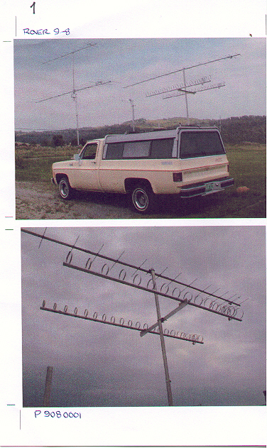
"Rover9-8" - This is the truck "dummied up" in antenna configuration prior to setting off for Burke Mt., VT for the September contest. (No… we certainly don’t go whizzing down the road like this!)
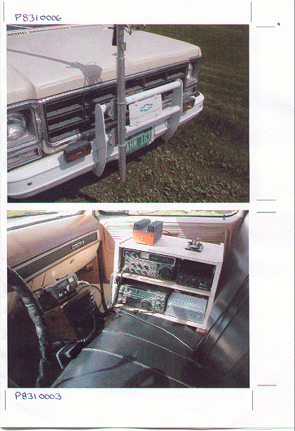
"P8310006" - This is the front mast mount that has been on this truck in one form or another since it’s acquisition. This truck came with the bumper over-rider… and the two cross bars gave me the idea of using universal cross-plates to attach a mast. That assembly is very rugged, so lends itself well to this arrangement. The last iteration of this thing is a "permanent" piece of 2" heavy wall aluminum pipe attached. In the bottom of that pipe is a cross bolt. The rotator mast has two notches that mate with that cross bolt. You simply insert the mast… and it locks into place with no additional attaching hardware required. The whole thing takes less than a minute to erect the mast, rotator and antennas. (Not counting attaching the antennas to the upper rotating portion of the rotator system.)
"P9080001" - Close up view of the 432/903/1296 antennas used in the September contest.
"P8310003" - Inside the cab, looking at the 222/432 module. The module on the center console is a Kenwood TR751/Amplifier package that "quick installs" on the center hump.
This package was replaced with the Icom 746 for 6M/2M operation for this contest.
Page 2:
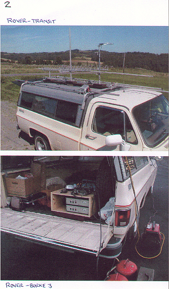
"Rover-transit" - This is the truck configured in the "travel" mode. Antennas, rotors, masts, etc. are stowed low on their mounts, or "bungee’d" to the cap racks. More on the "center spine" antenna mounts later.
"Rover-Burke3" - This is a rear view of the truck on the mountain, showing the 903/1296 module package, and the Honda generator.
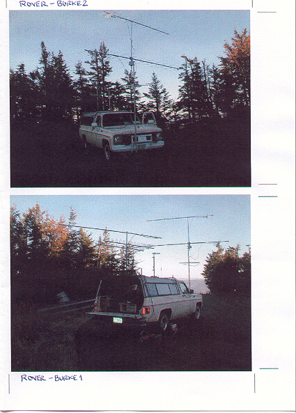
"Rover-Burke1 and 2" - This is the truck positioned on the mountain during the contest. The grid here is FN44BN, and the elevation is about 3300’ ASL. (Unfortunately, the lighting was poor when I took these photos.)
Page 3:
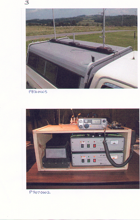
"P8310005" - This is a picture of the "center spine" used for antenna mounts on the bed cap. It is made with a length of 2X6 framing lumber. Three short pads, of the same material, are placed along it’s length. The pads are screwed and glued in position. Three one foot stubs of 1-3/8" aluminum tubing are installed in each pad. The holes to install the stubs were drilled with a spade bit, in a drill press, for good vertical alignment… and are glued in place with ordinary Elmer’s wood glue. Each stub is slotted at the top and a stainless hose clamp is used to hold 1-1/4" masts in place.
"P9070002" - Closeup of the 903/1296 modular package. Driver/I.F. is aYeasu FT290R 2M all-mode, also used for microwave bands.
Page 4:
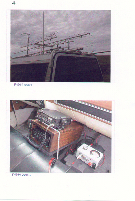
"P9140007" - Another view of the antennas in the "travel position".
"P9140006" - A closer and better view of the 2M modular package that normally goes with this truck in everyday use. TR751 and RFC 170W "brick" amp. One of the auxiliary batteries is shown here on the right hand floorboard. This is normally tied to the vehicle system, but can be charged from the generator as well.
Page 5:
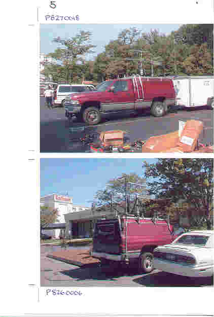
"P8270018" K6LEW’s "rovermobile" at the Eastern VHF Conference in August 2000. Don’t have a lot of details of this system… but it is obviously first rate.
"P8260006" Another view of K6LEW’s "rovermobile" setup. Professional quality throughout. Bristling with antennas. Did not talk with him about this system, so I have no details on bands, etc. He is part of the Grid Pirates multi-op group.
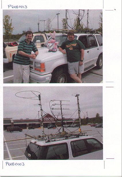
"P6080013" N1JEZ/N1MJD rover operation, along with their Eveready Bunny mascot.
One of the top rover systems in the country, based out of Vermont.
"P6080006". More N1JEZ/N1MJD stuff. This picture is inferior to one of the antenna system, already on the web site. These pictures were taken early summer before I had my truck set up in its present expanded configuration.
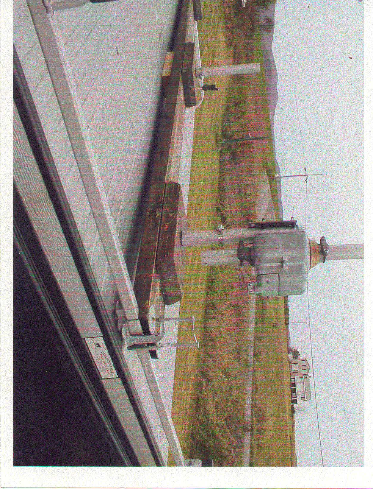
Glossy print: Large closeup of roof rack antenna mounts. 2X6 plank has notches cut into each end that slip over the roof rack bars, and held in place with "C" clamps. "C" clamps must be checked regularly for tightness, as they can work loose from vibration and wood shrinkage. Shown is one of the Alliance U100 rotators just installed. The forward mount pretty much carries the KB6KQ (New style) 2M "halo", and a pair of 432 "halos". The rear mount will be devoted to 432/903/1296. The center mount is for "miscellaneous" antennas, or possibly travel stowage for the three rear antennas.
6M/2M and 222 are run on the front bumper mount. The cab roof has a Motorola type mount for vertical whips. Currently running a 31" Antenna Specialists for 6M… which has worked out surprisingly well for a short, loaded 6M vertical antenna.
A similar, smaller scale "plank" type mount was run on my 1995 Ford Ranger work truck for several years, mainly with "halo" type antennas for 6M/2M. But also had a selection of whips on the cab roof… including the 31" A/S antenna for 6M… and many, long range QSO’s made in 6M mobile operation over a period of many years.
I’ve run many types of mobile "halo" antennas over the years on both 6M and 2M. But that’s another story.
L. L. Filby (K1LPS/Vermont)
FN34wl, and wherever…