|
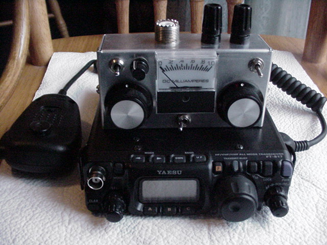
I wanted to build a small qrp tuner for my Yaesu FT-817 that did not require power and included a resistive swr bridge with a meter indicator instead of a led. The EMTECH ZM-2 is a great little Z-match tuner that includes an led indicator and I in fact got my poly-capacitors from EMTECH for $4.50 each. I spent quit a bit of time studying information from Charlie Lofgren, W6JJZ. I've included the original text here: z-match.txt. The depth of information from Mr. Lofgren is excellent and gives a good back ground for the Z-match design.
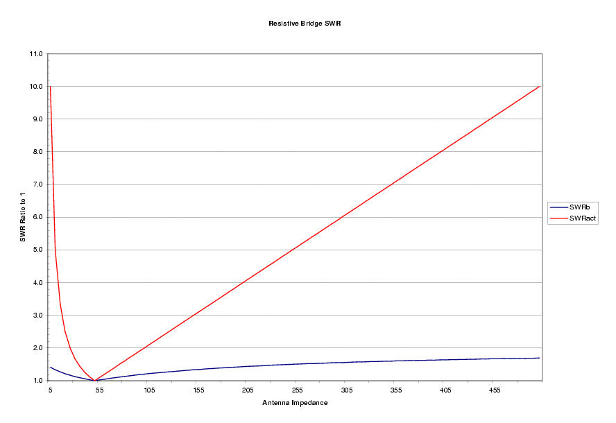
Why use a resistive bridge and why a meter? The resistive bridge provides protection to the output transitor by always providing an SWR of less than 2:1 no matter how bad the antenna match. To visualize the effect of the bridge see the following graph. The graph shows that an antenna impedance from 5-500 ohms has an SWR as high as 10:1 but the bridge will show an SWR of less than 2:1 to the radio. The meter reads a sample current rectified from the rf signal. The current is proportional to the imbalance in the bridge so although it is not calibrated it is linear and once the meter is adjusted for full scale (1ma) deflection the SWR can be accurately determined. From the graph it can be seen that a SWR of 1.2:1 in the bridge corresponds to a antenna SWR of 2:1 so a reading of less than .2ma corresponds to a SWR of less than 2:1. A meter provides a more accurate indication of the SWR than an led. The meter is adjusted to the output of the radio at a given frequency and will indicate accurately the degree of match that is just not possible by viewing the brightness of an led. The downside of a meter movement is the cost and possible mechanical damage compared to an led. I appreciate the accuracy of a meter, often there is more than one combination of tuner settings that will provide a good match, but one setting will be the best and provide a near perfect match.
My tuner was not the cheapest way to go, but I enjoyed piecing it together. First was selecting a case, I used an LMB #000 which worked great. Next the meter, a small 1ma Moduletec meter from Mouser. Everything was assembled using "dead bug" layout and connections, paying attention to the interaction between rf components. I let functionality drive the design, so some of the wiring paths are not the most direct but I wanted the tuner to be easy to use in my hands. The two main capacitor tuning knobs (the series cap, and shunt cap) are positioned so that they can be operated by the thumbs.
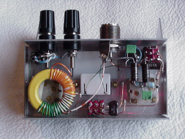
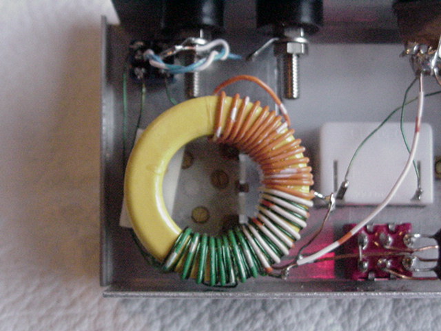
I chose to use the dual balanced output link configuration suggested by Mr. Lofgren. One link is a low impedance, the other a high impedance. This is a bit different than the ZM-2 configuration which uses one link that can be grounded for an unbalanced antenna feed using coax. I opted to go with the dual balanced link and use 300 twin lead to feed the antenna. Here is a closeup of coil. I have built a lightweight dipole to use with the tuner.
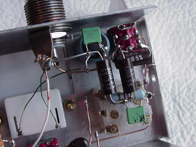
The swr bridge is set up for 2.5 watts, that is the nominal power out of the FT-817 when running on the internal batteries. The FT-817 will produce 5 watts (and maybe a bit more) on full power. The 2.5 watt setting insures that I don't over heat the 51 ohm resistors on the bridge and keeps the radiated rf low. The resistive bridge design is from GQRP sprat. The only difference is that I used a 5k potentiometer instead of a 10k and a 3.9k resistor instead of a 1k one for R4. The 5k setup works perfect for 2.5 watts and it allows for fine adjustment of the full scall deflection of the meter. The only disadvantage is that it doesn't provided enough resistance for 5 watts and too much for 1 watt. I prefer the fine adjustment since it is easier to operate if the tuner is my lap or being handheld (typical on a mountain top set up).
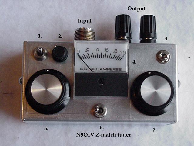
| 1. | Operate/Adj/Tune (3 position switch) |
|---|---|
| 2. | Full scale adjust for meter |
| 3. | Hi-Z/Lo-Z output coupling (changes tap on coil) |
| 4. | 1ma meter (0ma is 1:1 swr, 1ma is 2:1 swr in the bridge -see text for explanation.) |
| 5. | Series capacitance |
| 6. | Add series capacitance: One section of series cap/Both sections of series cap/Both sections plus 500pF (3 position switch) |
| 7. | Shunt capacitor |