Current Projects:
- 3-Meter Impedance Tester
- Ramsey 220 MHz Kit
- '98 September VHF Contest
- High Gain, Low Impact Backpacking Antenna
3-Meter Impedance Tester -
"The Antenna Experimenter's Guide" by Peter Dodd, G3LDO has a very good description of the 3-meter method for measuring impedance. I built one in a few hours using 1N4150 diodes from Dan's Small Parts. It works better than I had dared to hope for, and I highly recommend it. I had been struggling to tune a rubber ducky antenna for my HT (to replace one I lost), and could not get a good match using a SWR meter. The 3-meter measures the actual impedance, so you get a much better picture of the antenna impedance.In the end what I found is that casual measurements of impedance (or SWR) are very misleading for HT's. I was comparing a commercial rubber ducky to my homebrew, mounted directly on the SWR meter, and I got poor impedances from both. So I added a length of coax, and held the antenna in about the position it was used in. The commercial rubber ducky had very close to 50 ohms resistance, but my homebrew was terrible. I added some wire to the ducky and got resonance, although it needs more series inductance to get better than a 2.0 SWR.
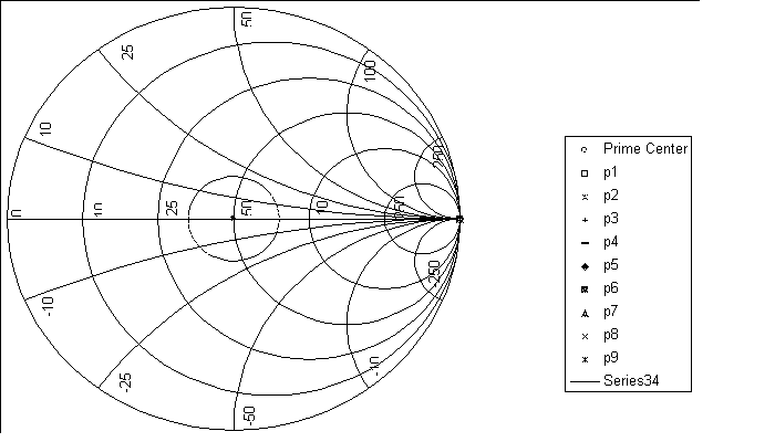
In doing this, I ended up developing a spreadsheet to interprete the 3-meter data. Click on the link and it will download in a zip file (WinZip 7.0). It was developed in Excel. A sample graph is shown below, and you can change the target SWR, view the graphic solution, correct for coax length, and of course get tabulated data.
To use the spreadsheet, just type in your data in the yellow cells. If you want to check the data, there is a separate sheet showing the graphical solution which helps to check the data and the calculated results. I used a different method to correct data than Peter Dodd used. I used an arithmetic average which should be more accurate than the iterative technique. If you see a correction, or high errors, then you should check the graphical solution. Sometimes the circles cross in several locations, and the analytical technique picks the wrong triangle. I have seen this occur with a high reactance load, but it can occur under other conditions. Checking the graphic solution identifies this problem quickly.
I also added a Smith Chart to the spreadsheet. The Smith Chart was set up to be used for other purposes also. Someday I may include functions to allow graphic problem solving on it.
Download 3-Meter Excel Spreadsheet

Ramsey 220 MHz Kit -
I was given a half built board, found the problem and finished the kit. It works, but there is no activity in our area. I have a 220 MHz magnetic mount car top antenna for it. I enjoyed building the kit, and would like to trade it for other kits that someone didn't finish. I bought the 2m version and have finished that also. I found that the RF test point on the low pass board did not provide accurate power readings. I was getting about 1/10 the voltage that the manual said (1.5 v instead of 12- 15 v per the manual). I checked the power output with an RF power meter and found out that I was getting the rated power output. That, and a few other typo�s, are the only complaints that I have with the Ramsey kits.
'98 September VHF Contest -
Last year my brother Pete, K6TJ, my brother Matt, KD6DTJ, my sister Til, KD0QIH and I went to Santa Rosa Island off the southern California coast on a boating trip, and worked the contest from Grid CM93. The only land in that grid is small parts of Santa Rosa and San Miguel Islands. It part of the Channel Islands National Park, so every thing has to be landed through the surf in a small boat, back packed up the hills (or mountains). The park ranger must have run across Hams before, because he was very suspicious of our adventure, and basically prohibited just about anything except HT's. No ground disruption, stay to the trails, antennas must not be visible from a distance, etc. We were able to satisfy him, and had a good time. On 2m, using the 4 element quad described in the ARRL Antenna Handbook, we were able to make some good contacts throughout southern California. We were also able to copy stations in the San Francisco area, but we could not break through to make a contact.Here is the view from the Torre Pines towards the Northwest Anchorage:
The conditions were exactly the way the sailing guides said. The wind was light in the morning, building through the day, and blew 25 to 30 knots all night! The campground was empty except for Pete and Matt, and has wind shelters which make it more comfortable than the boat. The NPS has made the ranch remove the cattle from the island because of water polution, but they still let the ranch host elk hunts. They do not allow hiking into the back country during the elk hunts, which seriously limits the options during the fall.
This year we are hoping to return to Santa Rosa Island for the September contest, with better antennas, and a higher location. Our goal is to make contacts in the SF area.
High Gain, Low Impact Backpacking Antenna -
I have not found an antenna suitable for mountain topping that does not disturb the ground and meets our gain requirements.