The K7CVT two-meter kilowatt amplifer
I built this amplifier about 1973 but the photos were taken after the amplifier had been in service for many years and just before I sold it to another ham. I sold it after building a replacement "W6PO" amplifier design that used the Eimac 8877.
The photos aren't the best quality, as they were snapped quickly as an afterthought before delivering the amplifier to the new owner, and after 30 years they had degraded somewhat before I scanned them.
I developed this design after reading the article by K2RIW that described a 432 MHz amplifier using two tubes in parallel, and prior to the publication and subsequent production of the W2GN version for two-meters. Prior to building this amplifier I had used an amplifier that I built in about 1965 that used a pair of 4CX250s in the more common push-pull configuration. This amplifier uses a pair of 4CX250F external anode metal ceramic tubes.
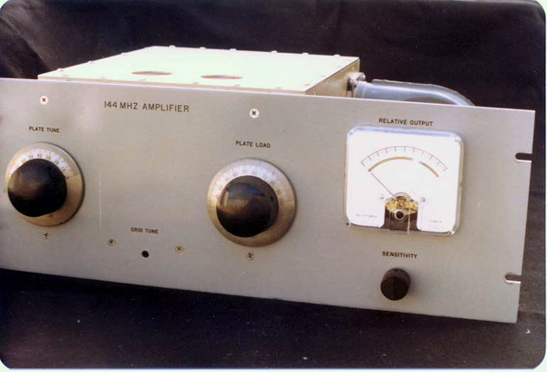
Front view.
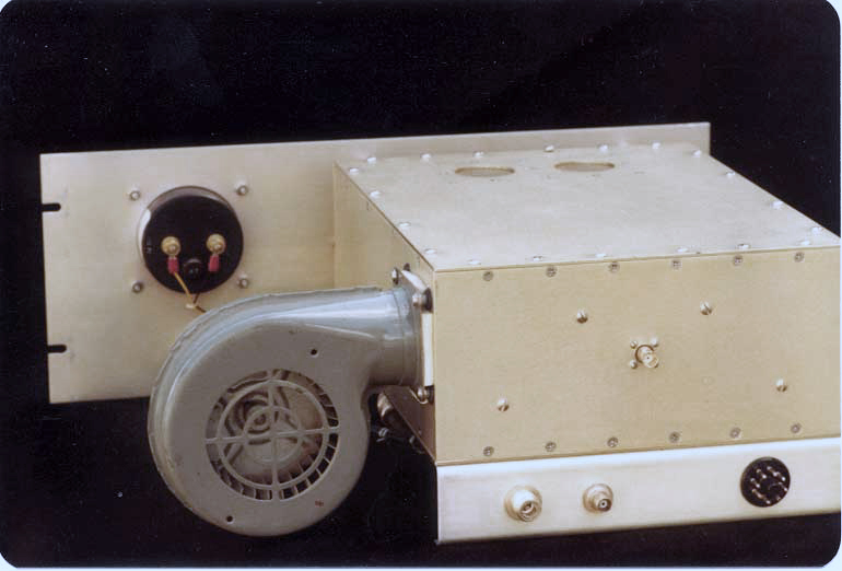
Rear View.
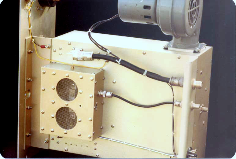
Bottom view.
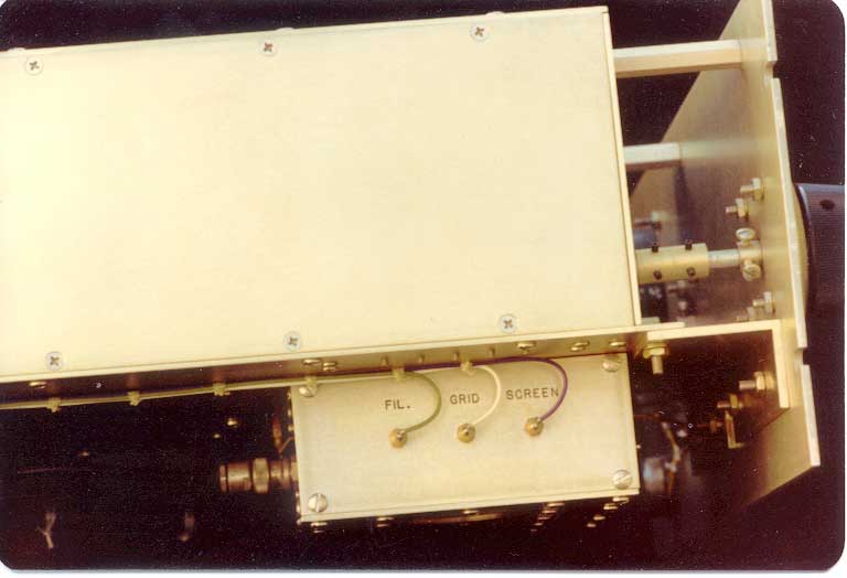
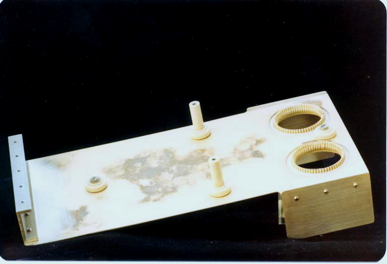
Side view. The nomenclature on the grid compartment is engraved and filled with permanent ink.
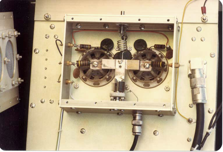
View of the inside of the grid circuit compartment. The matching circuit is basically a low-Q parallel tuned circuit comprised of the shunt capacitance of the tubes and a parallel inductor. The inductance is varied with a series capacitor to ground and the input is coupled via a variable capacitor. The circuit is resistively loaded by the parallel 510 ohm resistors.
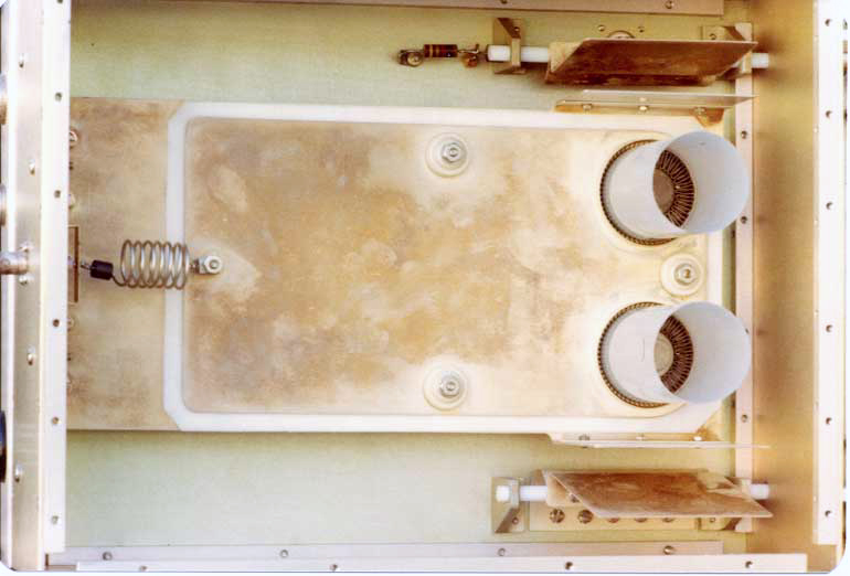
View inside the anode compartment. The circuit consists of a asymmetric stripline shorter than 90 degrees long, brought to resonance by a parallel tuning capacitor. The output coupling is via a variable capacitor. The capacitors are "flapper" type with one fixed plate and one movable plate. The movable plates are mounted on Teflon© shafts and driven from the front panel with reduction knobs that also serve to provide friction against unwanted rotation. The output coupling capacitor is at the top in this view, and the tuning capacitor is at the bottom. The high voltage is supplied through the anode rf choke to the left in the picture. The chimneys are made of mylar sheet. Cooling air pressurizes this compartment and the air is forced through the tube anode cooling fins and the chimneys to exit the enclosure. A small amount of air also bleeds through the tube sockets and out of screened holes in the grid enclosure, cooling the tube bases. This view also shows the construction method for the enclosures. They are constructed primarily of flat 0.062" 6061-T6 aluminum sheet joined at the edges with solid aluminum square bar stock, drilled and tapped for machine screws. All aluminum is treated with a chemical conversion passivation. (Alodine)
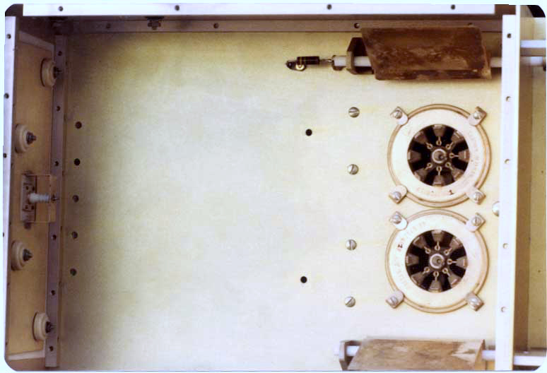
The anode compartment with the stripline removed. At the left is the high voltage bypass capacitor. The capacitor is constructed similarly to the stripline. A piece of Teflon© sheet is sandwiched between the wall of the enclosure and a brass sheet that is connected to the HV connector.
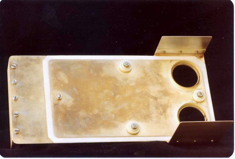
Top view of the plate circuit stripline. The line is a sandwich of silver-plated brass sheet with a Teflon© sheet insulator. The upper sheet carries plate voltage while the lower sheet is at dc ground potential. The "ears" are one half of the plate tuning and loading capacitors.
Bottom view of the stripline. The shorting bar is to the left. The ceramic insulators support the line and hold the sandwich together.
Not shown is the high voltage, screen and grid bias power supply and metering. The tubes were operated class AB1, (zero grid current), about 300 VDC on the screens and 2200 volts or so on the anodes. With the heavy resistive loading on the grids and the excellent isolation provided both by the integral screen bypass capacitors of the air system sockets and the enclosures, the operation was rock stable without neutralization. Efficiency ran about 55-60%. Lots of folks claim higher efficiencies, but they either lie or are running way out of the linear region.