A small square loop antenna
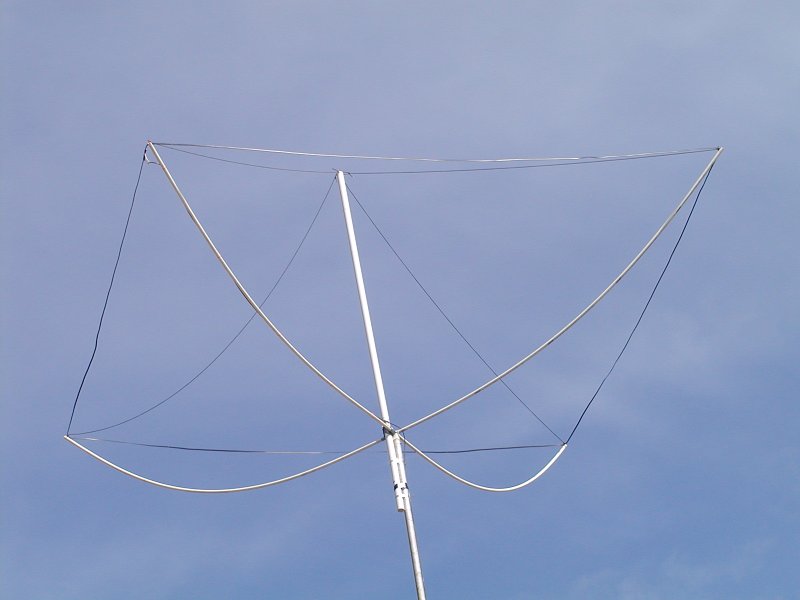 |
| In the May/June issue of QEX, Robert K Zimmerman, Jr, NP4B described a uniform current loop radiator.
The antenna immediately caught my eye and a 20 meter version was soon ready for testing.
The fiberglass rods described in the article were not available locally so I decided to try CPVC
which the local hardware store has in abundance. 1 inch CPVC was used for the spreaders, which
turned out to be too flexible to support the 300 ohm twin lead by themselves. The 2 inch piece
of CPVC was added as a center vertical support and para-chord guy-lines stabilize the spreaders.
A plastic block was hammered into the end of the mast and a 1/4-20 bolt goes down through the center
CPVC cross into the plastic block. The vertical support is held to the mast with hose clamps.
|
 |
Well, the best laid plans...
I lowered the antenna to make some adjustments and while pushing the mast back
up, a very large wind gust struck the antenna and folded the stainless steel portion of the mast in half. The
antenna struck the roof of the carport and broke one of the PVC arms. I shrugged my shoulders and thought "Oh,
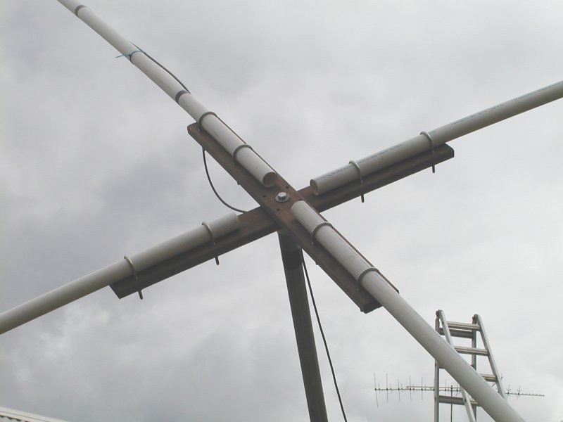
well, I wanted to try a new design anyway." The new design uses two pieces of 1 x 4 cedar to form a center
cross with a center bolt holding the cross to the mast. 1-1/2" PVC pipe is used for the arms which slide
under the U-bolts to adjust the tension on the wire.
|
 |
| This antenna is a joy to work with, comparing it to a dual band (80/40 meter) trap dipole, the loop has a
wonderful noise immunity. Man made noise drops dramatically when switching from the dipole to the loop and
atmospheric noise decreases a little. The omni-directional pattern is a joy after the dipoles deafness to
the sides and the antenna's small physical size allows it to fit in any convenient location, with a single
support.
|
 |
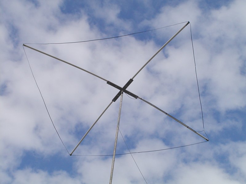
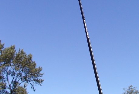
| I built a 6 meter version of this antenna for the sake of convenience in experimenting with construction and
tuning techniques. Here are the details on that antenna. The above graphic illustrates the concept of
alternating cuts, high side, low side, to form the series capacitive loading effect.
|
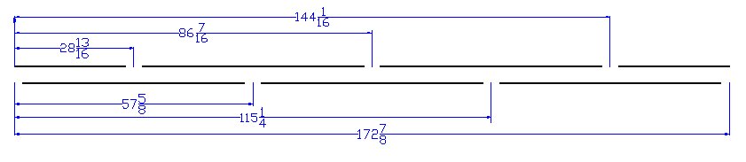 |
| Radio Shack Foam Core Twin Lead is used, these numbers contain an allowance for the velocity factor of that
wire. Start by laying the wire out straight and cutting to these dimensions. These dimensions resulted in a
frequency of resonance at 49 MHz. It is a good idea to aim a little low in frequency, raising the point of
resonance is accomplished by trimming the gaps a little wider until resonance moves up to the desired
frequency. Make the gaps about 1/2" wide to start with, my antenna settled at 50.2MHz when the gaps
had been trimmed to about 2" wide.
|
 |
| A simple plywood cross was cut on a band-saw to form the center support. The PVC arms are coped on the ends
with a wood-rasp to hold the Twin Lead Wire. I pushed the arms out from center to adjust the tension on the
wire and then installed the woodscrews through the PVC pipe.
|
 |
| Here is a look at the gap after it has been trimmed to move the resonant frequency up.
|
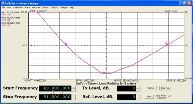 |
| A sweep from the Vector Network Analyzer shows that the 2 to 1 SWR points are about 1.6Mhz apart.
I leave the 6 meter rig set to this antenna with the squelch on for quiet monitoring of the calling
frequency. The omnidirectional pattern is great for monitoring and this antenna does not require the
complexity of construction or maintenance of the Halo with its gamma match requirement.
|