The Roanoke Doppler Plus (RDP)
The Roanoke Doppler Plus is a kit put together by Marty Mitchell N6ZAV. The RDP is a VHF and UHF radio direction finding system based on a project in TRANSMITTER HUNTING - Radio Direction Finding Simplified by Moell and Curlee. The kit was complete with components and PCB's.
However it required the builder (yours truly) to build an antenna array. After several unsuccessful attempts at building the copper clad plywood antenna array, I was glad to see the improved Doppler array article originally published by Joe Moell K0OV in the April 1995 Homing In column of 73 Magazine. An on-line resource is currently available at the Homing In webpage. Following the article's lead, I found some mag mount CB antennas that I could dissect and modify for use with the RDP.
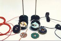
Below is a before and after comparison of the original CB antenna. The original CB antenna is on the right and the modified antenna on the left. The black donuts looking things are magnets that were popped out of the base. The CB antenna PCB was replaced with similar shaped copper clad board which the components were mounted on.
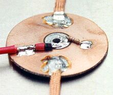
In this close up of the copper clad board notice the etched ring around the center antenna mounting hole. The required resistor is soldered between the center the inner and outer rings. Although hard to see, the other lead of the diode (black with red heat shrink) is soldered to the center conducter of the RG-188 coax (red wire on left). The shield of the coax is soldered to the outer ring of the copper clad board. The two strips of copper braid were fed through the holes in the magnet to thin strips of copper foil. The foil was sandwiched between the magnets and conductive foil tape that covered the base of each of the four antennas. The telescoping elements were extended to 19 inches for use on 2 meters
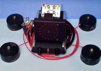
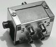
The switching box was carefully constructed with close attention being paid to component lead lengths.
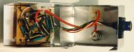
This is a picture of the finished switching box. The four BNC's are labeled for their respective antenna. The control and switching voltage is supplied through the connector on the left. The BNC on the back of the box supplies the RF signal to the receiver.
The switching box was mounted inside the van to keep it out of the elements. The antenna coax was fed around the van rear door and connected to the switching box.
Once built, I laid out the doppler antenna array on my RDF Van roof and marked their position with a permanent marker. This way I could easily change bands by repositioning the antenna bases and change the length of the telescoping antenna elements.

Back to the N6QAB home page
This page updated on 02/06/99